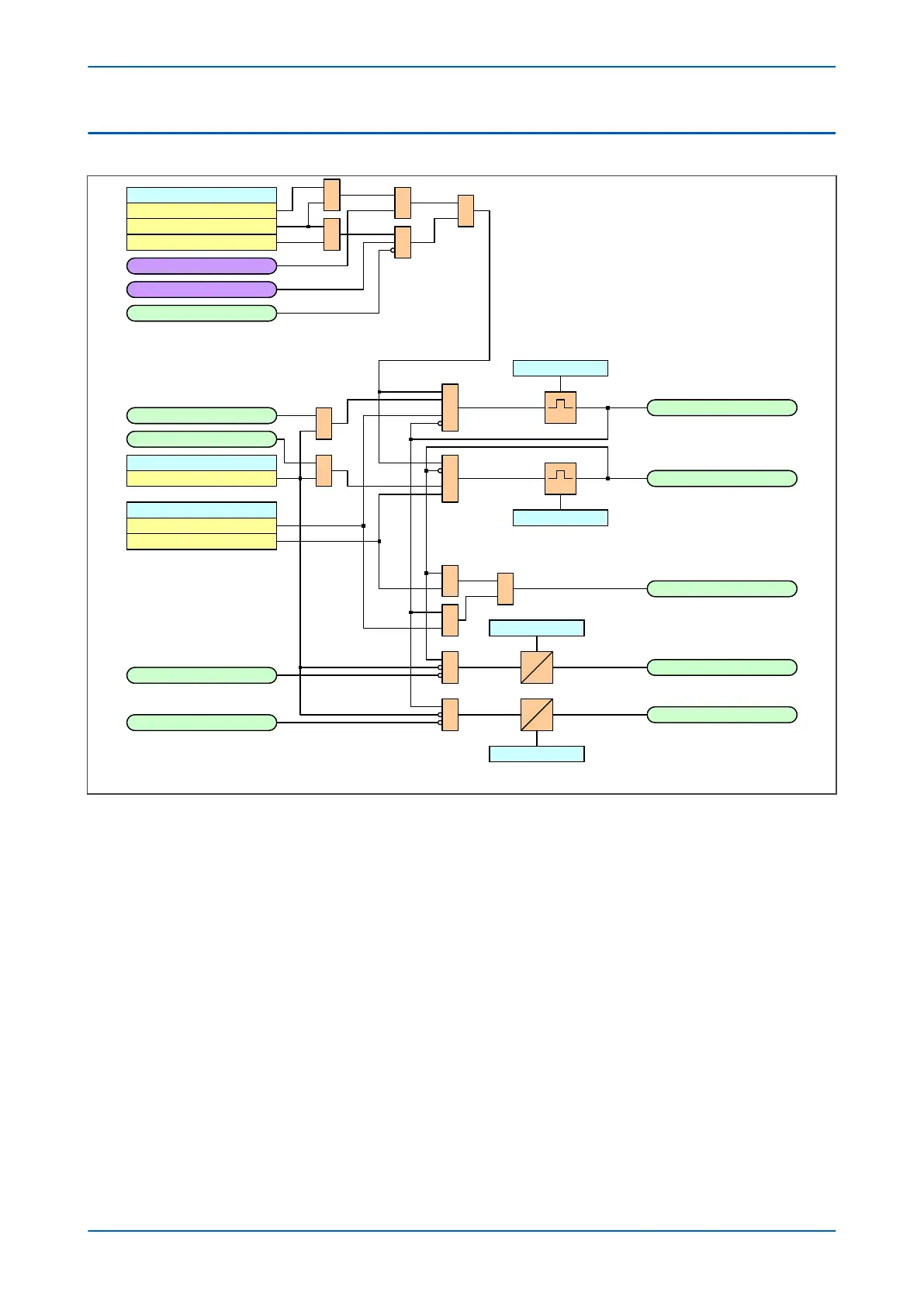
V01285
SWI1 Co ntrol bySWI1 Control by
Loca lLoca l
RemoteRemote
Loca l+Re moteLocal+Remote
1
Blk Rmt SWI1 OpsBlk Rmt SWI1 Ops
Loca lLoca l
RemoteRemote
1
&
&
1
SWI1 Status OpnSWI1 Status Opn
SWI1 Status ClsSWI1 Status Cls
SWI1 Status InptSWI1 Status Inpt
NoneNone
1
1
&
&
SWI1 Trip/CloseSWI1 Trip/Clo se
CloseClose
TripTrip
SWI1 Co ntrol TrpSWI1 Control Trp
SWI1 Co ntrol ClsSWI1 Control Cls
SWI1 Trp P uls TSWI1 Trp Puls T
SWI1 Cls Puls TSWI1 Cls Puls T
&
&
&
&
1
SWI1 Input AlmSWI1 Input Alm
SWI1 Status OpnSWI1 Status Opn
SWI1 Status ClsSWI1 Status Cls
t
t
0
0
SWI1 Cls Alrm TSWI1 Cls Alrm T
SWI1 Trp A lrm TSWI1 Trp Alrm T
SWI1 Trip FailSWI1 Trip Fail
SWI1 Cls FailSWI1 Cls Fail
Note: This diagram does not show a ll switches. Other switches f ollow simila r principles.Note: This diagram does not show a ll switches. Other switches f ollow simila r principles.