V00641
a) capacitive and inductive currents with resistive components
N
b) Unfaulted line
c) Faulted line
Operate
Restrain
Zero torque line for 0° RCA
Zero torque line for 0° RCA
Operate
Restrain
I’
L
Resistive component
in grounding coil
Resistive component
in feeder
(IAH1 + IH2 + IH3)’
3V
0
BC
A
-I
H 1
- I
H2
I
L
IR1 = IH1
IR 3
I
R3
= I
F
+ I
H3
= I
L
- I
H1
- I
H12
V
res
= -3V
0
V
res
= -3V
0
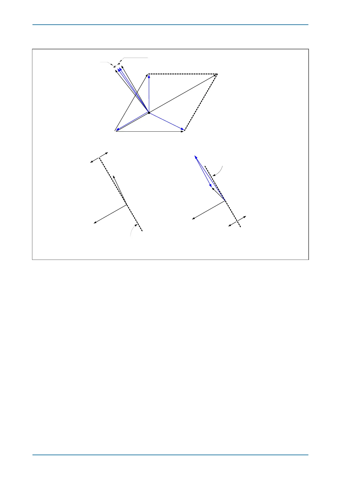
Figure 55: Practical case:- resistance present in XL and Xc
The figur
e above shows the relationship between the capacitive currents, coil current and residual voltage. Due to
the presence of resistance in the feeders the healthy phase charging currents are now leading their respective
phase voltages by less than 90°. In a similar manner, the resistance present in the earthing coil has the effect of
shifting the current, IL, to an angle less than 90° lagging. The result of these slight shifts in angles can be seen in
part b and c in the figure above.
The residual current now appears at an angle in excess of 90° from the polarizing voltage for the unfaulted feeder
and less than 90° on the faulted feeder. Therefore, a directional relay with a characteristic angle setting of 0° (with
respect to the polarizing signal of -3Vo) could be applied to provide discrimination. The healthy feeder residual
current would appear in the restrain section of the characteristic but the residual current on the faulted feeder
would be in the operate region.
In practical systems a resistance is inserted in parallel with the earthing coil. This increases the level of earth fault
current to a more detectable level. It also increases the angular difference between the residual signals to help the
application of discriminating protection.
Chapter 6 - Current Protection Functions P24xM
128 P24xM-TM-EN-2.1