2 SOFTWARE DESIGN OVERVIEW
The range of products based on the <platform> platform can be conceptually categorised into several elements as
follows:
● The system lev
el software
● The platform software
● The protection and control software
These elements are not distinguishable to the user, and the distinction is made purely for the purposes of
explanation.
V00300
R
e
c
o
r
d
s
P
r
o
t
e
c
t
i
o
n
a
n
d
c
o
n
t
r
o
l
s
e
t
t
i
n
g
s
Protection and Control Software Layer
Fault locator
task
Disturbance
recorder task
Sampling function
Control of output contacts
and programmable LEDs
Sample data + digital
logic inputs
System Level Software Layer
System services (e.g. device drivers) / Real time operating system / Self-diagnostic software
Control of interfaces to keypad , LCD, LEDs,
front & rear ports.
Self-checking maintenance records
Hardware Device Layer
LEDs / LCD / Keypad / Memory / FPGA
Protection Task
Programmable &
fixed scheme logic
Fourier signal
processing
Protection
algorithms
Supervisor task
Platform Software Layer
Event, fault,
disturbance,
maintenance record
logging
Remote
communications
interfaces
Front panel
interface
(LCD + Keypad)
Local
communications
interfaces
Settings database
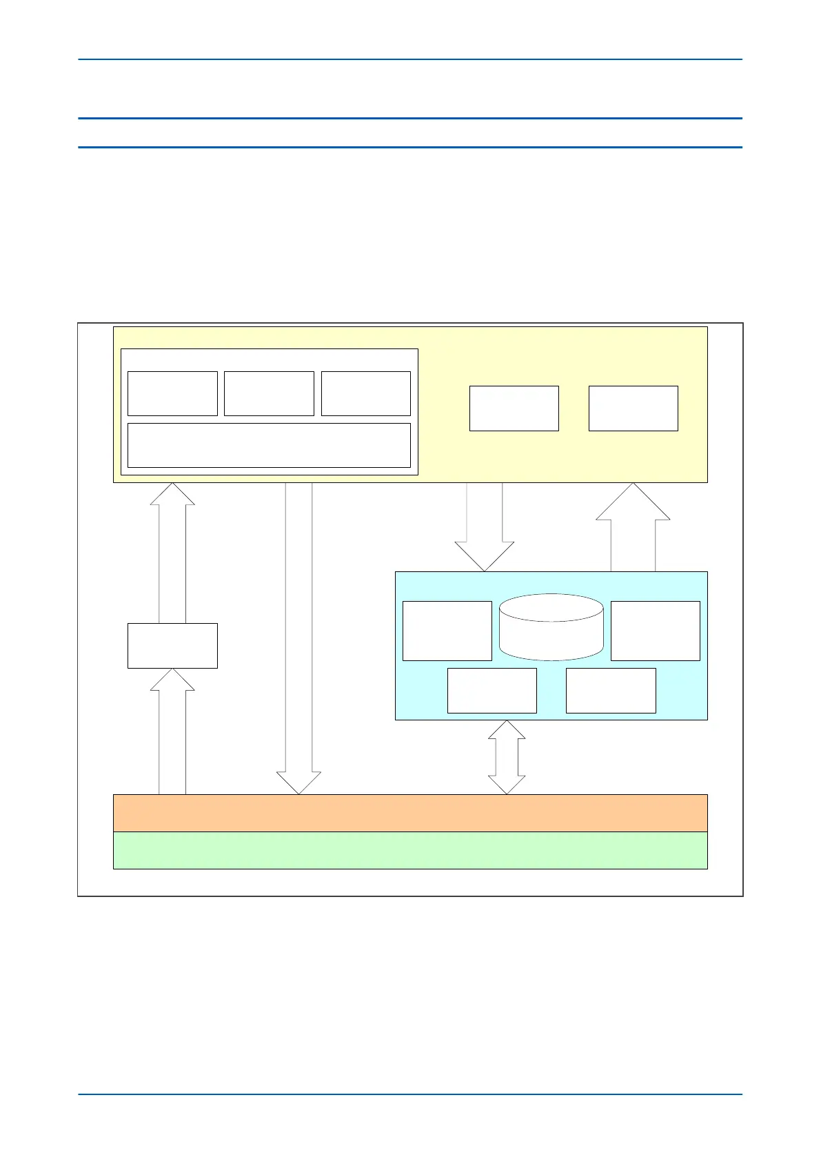
Figure 13: Software structure
The softw
are can be divided into a number of functions as illustrated above. Each function is further broken down
into a number of separate tasks. These tasks are then run according to a scheduler. They are run at either a fixed
rate or they are event driven. The tasks communicate with each other as required.
Chapter 4 - Software Design P24xM
46 P24xM-TM-EN-2.1