10 SWITCH STATUS AND CONTROL
All P40 Agile products support Switch Status and Control for up to 8 switchgear elements in an IEC61850
substation. The device is able to monitor the status of and contr
ol up to eight switches. The types of switch that
can be controlled are:
● Load Break switch
● Disconnector
● Earthing Switch
● High Speed Earthing Switch
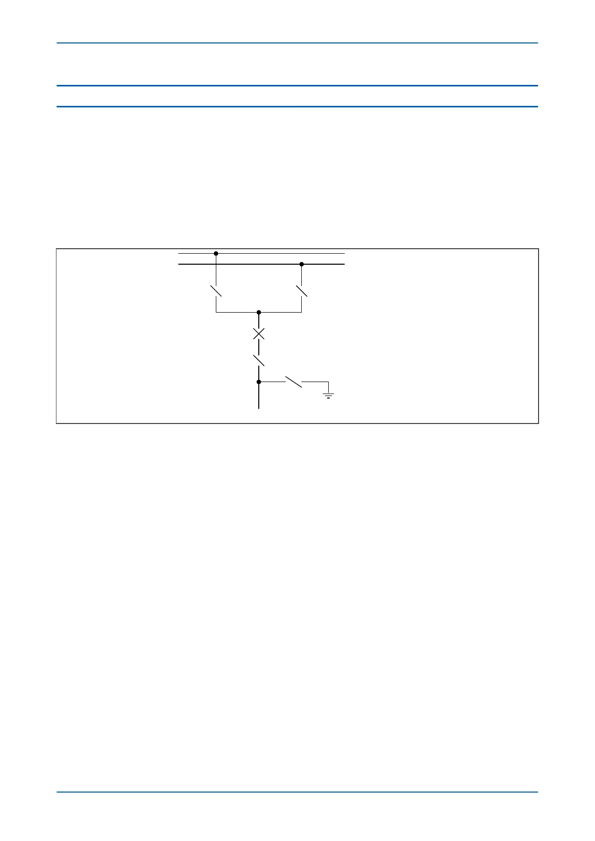
Consider the following feeder bay:
V01241
XSWI1 XSWI2
X
SWI3
XSWI4
XCBR
L
egend:
XSWI1 = Disconnector 1
XSWI2 = Disconnector 2
XSWI3 = Disconnector 3
XSWI4 = Earthing Switch
XCBR = Circuit Breaker
Figure 127: Representation of typical feeder bay
This bay shows four switches of the type LN X
SWI and one circuit breaker of type LN XCBR. In this example, the
switches XSWI1 – XSWI3 are disconnectors and XCSWI4 is an earthing switch.
For the device to be able to control the switches, the switches must provide auxiliary contacts to indicate the
switch status. For convenience, the device settings refer to the auxiliary contacts as 52A and 52B, even though
they are not circuit breakers.
There are eight sets of settings in the SWITCH CONTROL column, which allow you to set up the Switch control, one
set for each switch. These settings are as follows:
SWITCH1 Type
This setting defines the type of switch. It can be a load breaking switch, a disconnector, an earthing switch or a
high speed earthing switch.
SWI1 Status Inpt
This setting defines the type of auxiliary contacts that will be used for the control logic. For convenience, the device
settings refer to the auxiliary contacts as 52A and 52B, even though they are not circuit breakers. "A" contacts
match the status of the primary contacts, whilst "B" contacts are of the opposite polarity.
SWI1 Control by
This setting determines how the switch is to be controlled. This can be Local (using the device directly) remote
(using a communications link), or both.
SWI1 Trip/Close
This is a command to directly trip or close the switch.
SWI1 Trp Puls T and SWI1 Cls Puls T
P24xM Chapter 13 - Monitoring and Control
P24xM-TM-EN-2.1 267