2 REF PROTECTION PRINCIPLES
Winding-to-core faults can be caused by insulation breakdown. Such faults can have very low fault currents, but
they still need to be pick
ed up. If such faults are not identified, this could result in extreme damage to very
expensive equipment.
Often the associated fault currents are lower than the nominal load current. Neither overcurrent nor percentage
differential protection is sufficiently sensitive in this case. We therefore require a different type of protection
arrangement. Not only should the protection arrangement be sensitive, but it must create a protection zone to
protect the individual windings.
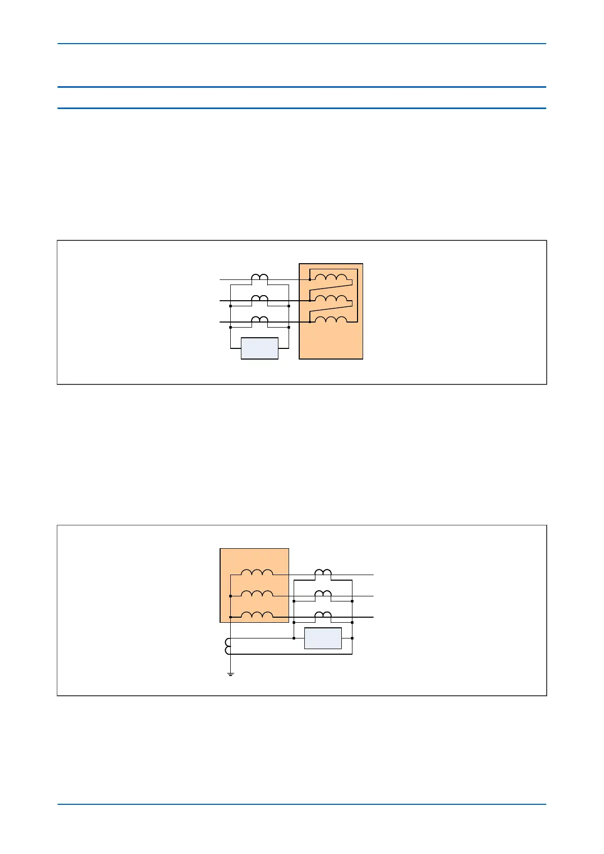
The following figure shows a REF protection arrangement for protecting the delta connected winding.
V00796
REF
protection zone
IED
A
B
C
REF
protection zone
IED
A
B
C
Figure 83: REF protection for delta connected winding
The curr
ent transformers measuring the currents in each phase are connected in parallel. The currents from all
three phases are summed to form a differential current, sometimes known as a spill current. Under normal
operating conditions the currents of the three phases add up to zero resulting in zero spill current. A fault on the
star side will also not result in a spill current, as the fault current would simply circulate in the delta windings.
However, if any of the three delta windings were to develop a fault, the impedance of the faulty winding would
change and that would result in a mismatch between the phase currents, resulting in a spill current. If the spill
current is large enough, it will trigger a trip command.
The following figure shows a REF protection arrangement for the star connected winding.
V00797
REF
protection zone
IED
A
B
C
REF
protection zone
IED
A
B
C
Figure 84: REF protection for star connected winding
Her
e we have a similar arrangement of current transformers connected in parallel. The difference is that we need
to measure the zero sequence current in the neutral line as well. An external unbalanced fault causes zero
sequence current to flow through the neutral line, resulting in uneven currents in the phases, which could cause
the protection to maloperate. By measuring this zero sequence current and placing it in parallel with the other
Chapter 7 - Restricted Earth Fault Protection P24xM
168 P24xM-TM-EN-2.1