5 SETTINGS GROUP SELECTION
You can select the setting group using opto inputs, a menu selection, and for some models the hotkey menu or
f
unction keys. You choose which method using the Setting Group setting in the CONFIGURATION column. There are
two possibilities; Select via Menu, or Select via PSL. If you choose Select via Menu, you set the settings group using
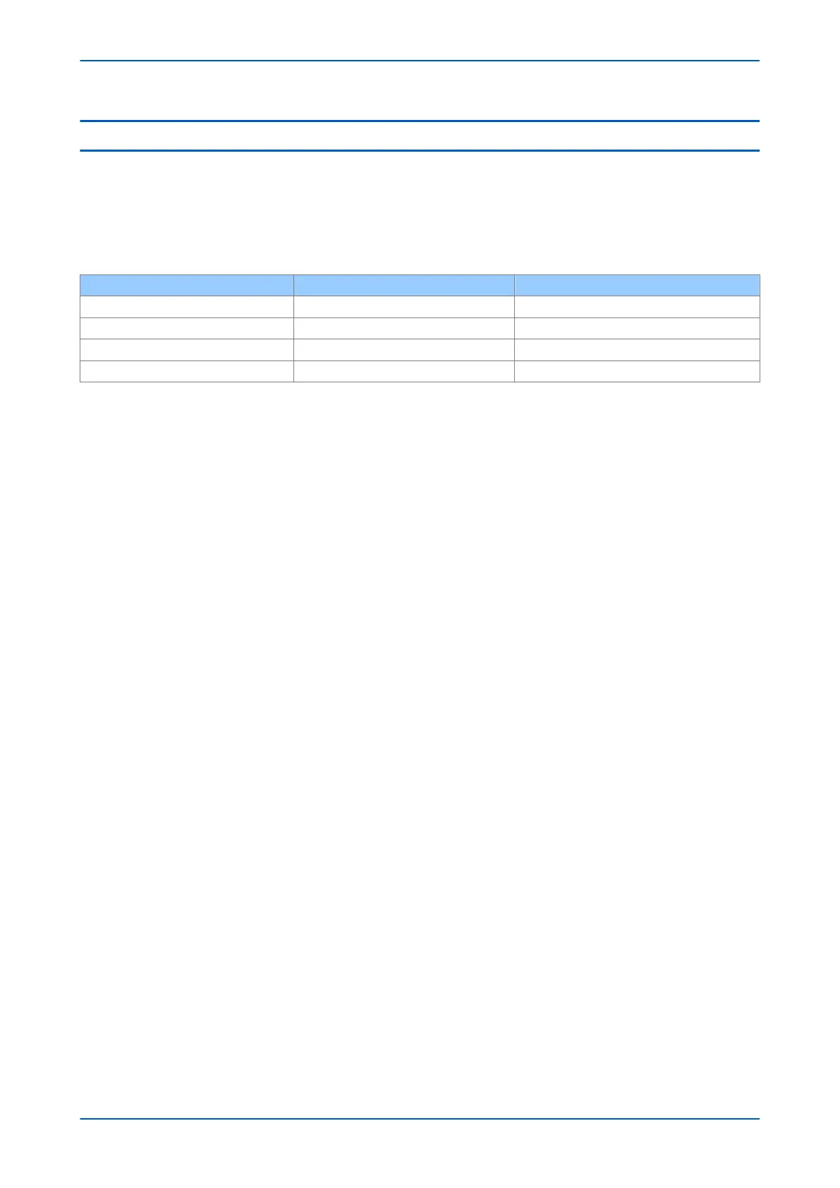
the Active Settings setting or with the hotkeys. If you choose Select via PSL , you set the settings group with DDB
signals according to the following table:
SG Select 1X SG Select X1 Selected Setting Group
0 0 1
0 1 2
1 0 3
1 1 4
Each setting group has its own PSL. Once a PSL configuration has been designed it can be allocated to any one of
the 4 setting gr
oups. When downloading or extracting a PSL configuration, you will be prompted to enter the
required setting group to which it will allocated.
P24xM Chapter 5 - Configuration
P24xM-TM-EN-2.1 69