2.2 DC SUPPLY MONITOR LOGIC
V01220
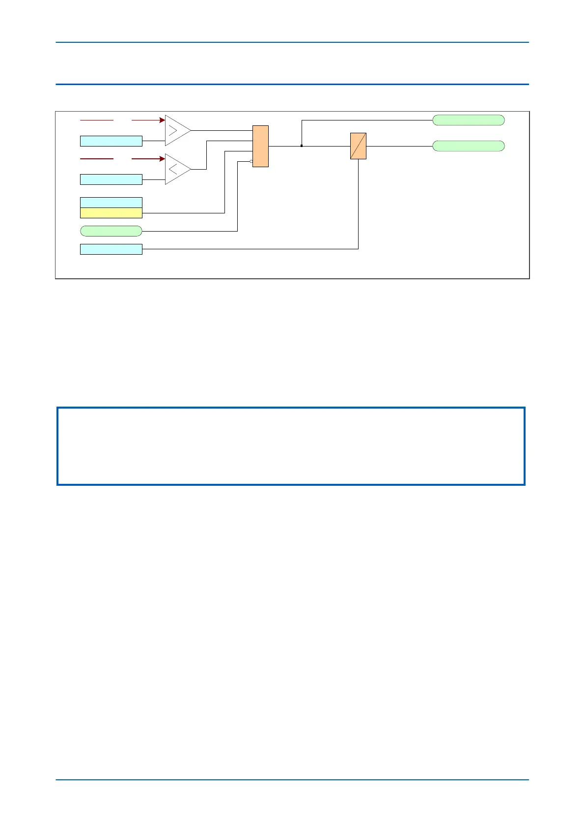
Vdc1 Lower Limit
Enabled
Vdc1 Upp er Limit
Vdc1 Status
InhibitDC SupMon
&
Vdc1 Start
Vdc1 Trip
Vdc
Vdc
t
0
Vdc1 Time Delay
Figure 131: DC Supply Monitor logic
The diagram abov
e shows the DC supply monitoring logic for stage 1 only. Stages 2 and 3 are identical in principle.
The logic function will work when the Vdc1 status setting cell is Enabled and the DC Supply Monitoring inhibit
signal (InhibitDC SupMon) is low.
If the auxiliary supply voltage (Vdc) exceeds the lower limit AND falls below the upper limit, the voltage is in the
healthy zone and a Start signal is generated.
The Vdc(n) Trip signals from all stages are OR'd together to produce an alarm signal DC Supply Fail.
Note:
The device's supercapacitor uses Vdc to provide charge and so may cause the voltage to dip below the Vdc lower limit (19.2 V)
during a system power-up sequence if fully discharged. This will trigger a lockout error. In this case, it will be necessary to
allow the supercapacitor to charge before attempting another power-up sequence. The supercapacitor may take several
minutes to become fully charged, depending on the AC/DC supply specification. With the supercapacitor charged, the next
relay power cycle will clear the lockout and the relay will boot and operate normally.
P24xM Chapter 14 - Supervision
P24xM-TM-EN-2.1 275