4 CABLES AND CONNECTORS
This section describes the type of wiring and connections that should be used when installing the device. For pin-
out details please r
efer to the Hardware Design chapter or the wiring diagrams.
Caution:
Befor
e carrying out any work on the equipment you should be familiar with the Safety
Section and the ratings on the equipment’s rating label.
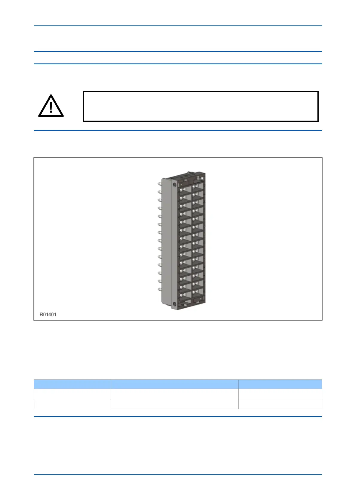
4.1 TERMINAL BLOCKS
The device uses MiDOS terminal blocks as shown below.
Figure 162: MiDOS terminal block
The MiDOS terminal block consists of up to 28 x M4 scr
ew terminals. The wires should be terminated with rings
using 90° ring terminals, with no more than two rings per terminal. The products are supplied with sufficient M4
screws.
M4 90° crimp ring terminals are available in three different sizes depending on the wire size. Each type is available
in bags of 100.
Part number Wire size Insulation color
ZB9124 901
0.25 - 1.65 mm
2
(22 – 16 AWG)
Red
ZB9124 900
1.04 - 2.63 mm
2
(16 – 14
AWG)
Blue
4.2 POWER SUPPLY CONNECTIONS
These should be wired with 1.5 mm PVC insulated multi-stranded copper wire terminated with M4 ring terminals.
The wir
e should have a minimum voltage rating of 300 V RMS.
Chapter 18 - Installation P24xM
388 P24xM-TM-EN-2.1