Time delays should be sufficient to override any transient dips in frequency, as well as to provide time for the
fr
equency controls in the system to respond. These should not be excessive as this could jeopardize system
stability. Time delay settings of 5 - 20 s are typical.
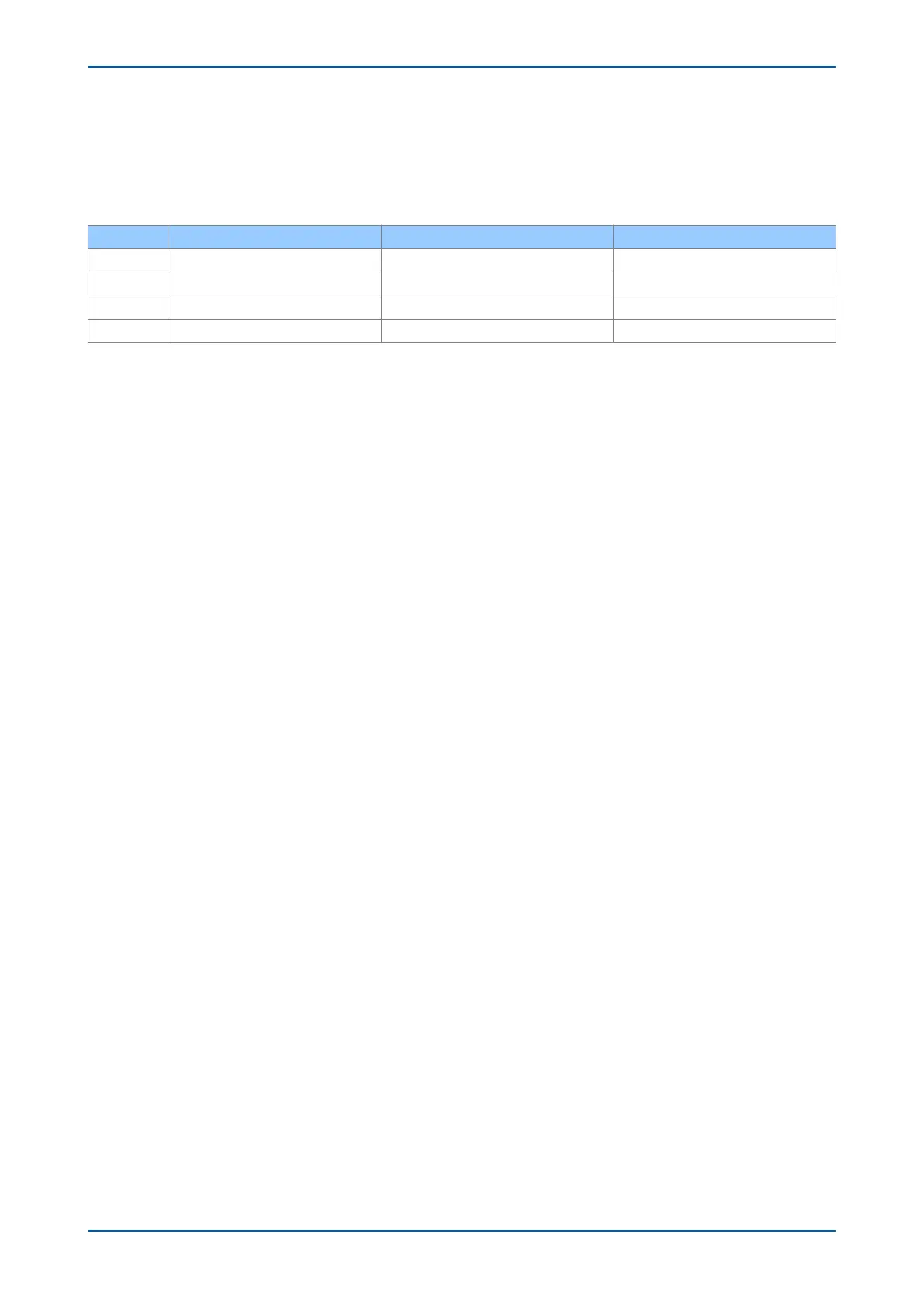
An example of a four-stage load shedding scheme for 50 Hz systems is shown below:
Stage Element Frequency Setting (Hz) Time Setting (Sec)
1 Stage 1(f+t) 49.0 20 s
2 Stage 2(f+t) 48.6 20 s
3 Stage 3(f+t) 48.2 10 s
4 Stage 4(f+t) 47.8 10 s
The relatively long time delays are intended to provide sufficient time for the system controls to respond. This will
w
ork well in a situation where the decline of system frequency is slow. For situations where rapid decline of
frequency is expected, this load shedding scheme should be supplemented by rate of change of frequency
protection elements.
Chapter 11 - Frequency Protection Functions P24xM
226 P24xM-TM-EN-2.1

 Loading...


