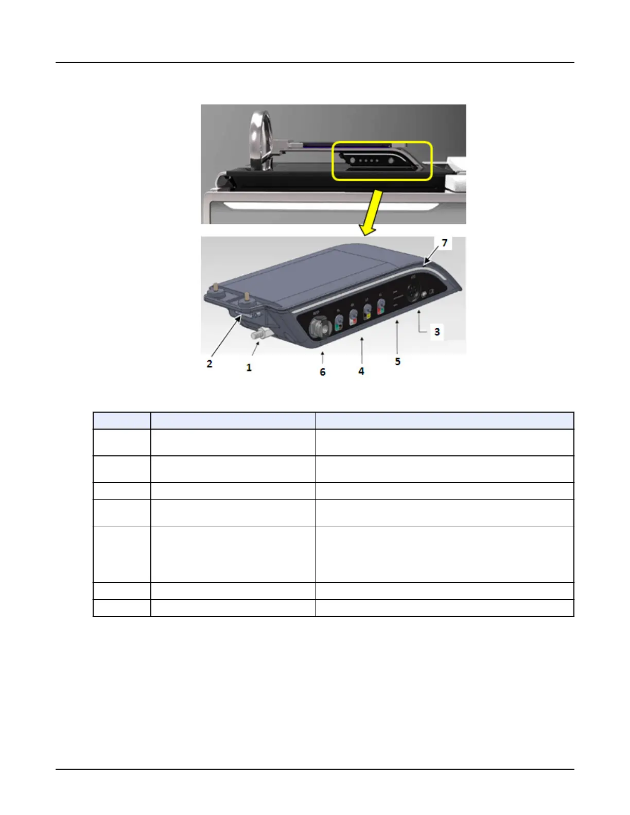
Illustration 13: Integrated Cardiac Module
Table 11: Integrated Cardiac Module Components
Number
Components Description
1 Functional Ground
Connected to the ground cable that connects to the cable retractor
below the cradle.
2 Network Interface Cable
Connected to the RS-422 communication cable that connects to the
cable retractor below the cradle.
3 6-Pin AAMI ECG Patient Cable Connector Connection used for the 4-lead patient cable.
4 4-Lead ECG Simulator
Connection used for the 4-leads when the simulator mode is re‐
quired.
5 Annunciator LEDs
POWER (Green LED) – Indicates that power is applied to the Cardiac
Module.
COMMUNICATION (Yellow LED) – Flashes when the Cardiac Mod‐
ule is transmitting and receiving data.
STATUS (Yellow LED) – Flashes when is operating normally.
6
Respiratory connector Connection used for the Respiratory hose into this connector
7 Light Pipe Light for room ambient.
3.5.2 External cardiac trigger monitor
If using the External ECG monitor (IVY 7800) instead of the ICM, follow the steps below:
1.
Locate the gantry’s left-rear plug-in panel.
Revolution CT User Manual
Direction 5480385-1EN, Revision 1
176 3 Gantry

 Loading...


