19
Names and Functions of Parts
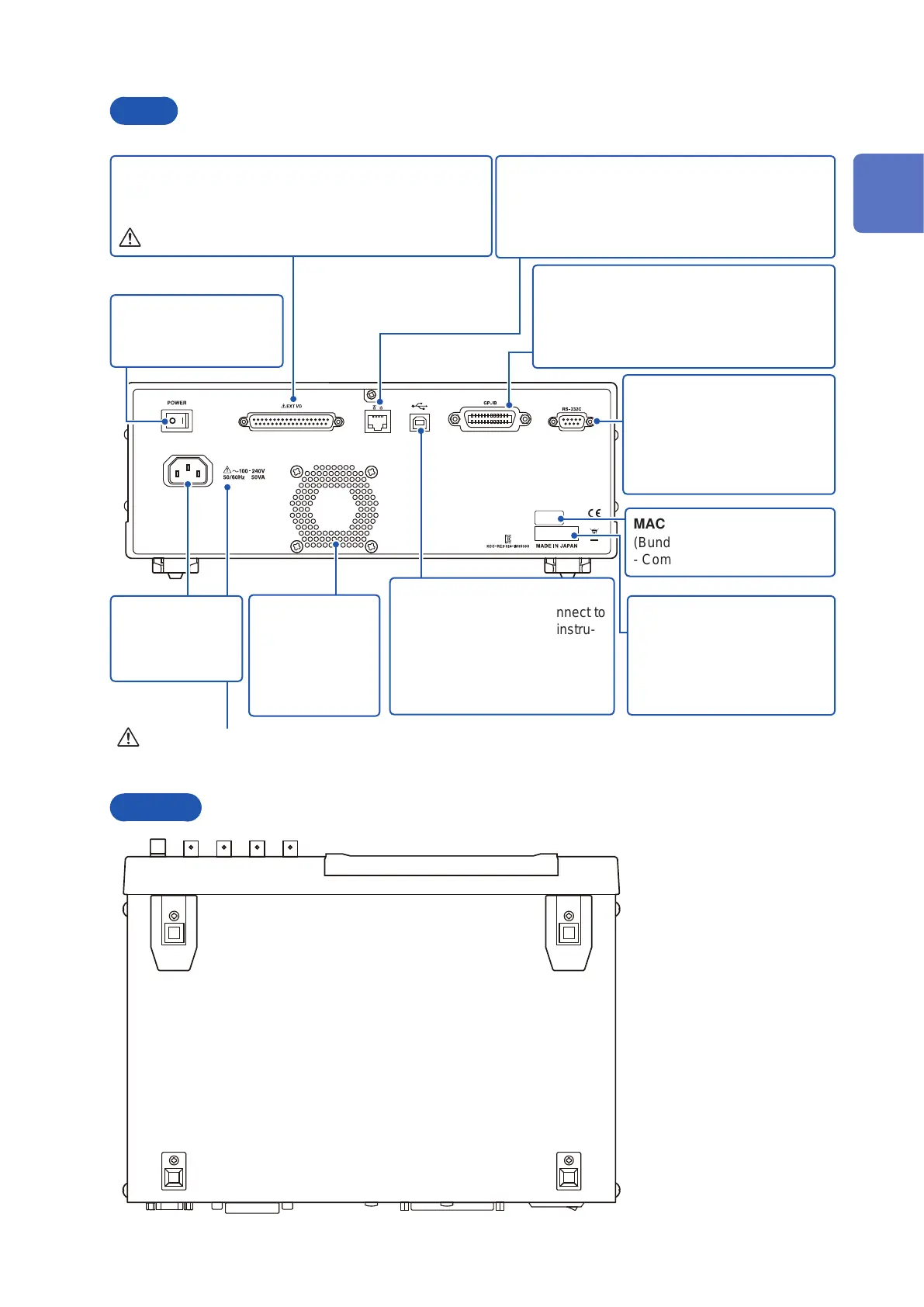
Rear
Main power switch
Turns the power on and
off (p. 36).
Rear USB connector
Connect a USB cable. Connect to
a computer to control the instru-
ment with communication com-
mands.
(Bundled LCR Application Disc -
Communications Manual)
Vent
Keep clear of ob-
structions.
Keep foreign
objects and other
material away.
GP-IB connector
Allows you to connect the instrument to exter-
nal devices using a GP-IB cable.
(Bundled LCR Application Disc - Communica-
tions Manual)
RS-232C connector
Allows you to connect the
instrument to external devices
using a RS-232C cable.
(Bundled LCR Application Disc
- Communications Manual)
MAC address of the LAN
(Bundled LCR Application Disc
- Communications Manual)
Manufacturer’s serial number
Shows the serial number.
Do not remove this label, as it
is required
for product support.
LAN connector
Allows you to connect the instrument to external
devices using a LAN cable.
(Bundled LCR Application Disc - Communications
Manual)
EXT I/O connector
Allows you to control the start of measurement and capture
judgment results by connecting a PLC or I/O board.(p. 162)
See “Before Connecting EXT I/O” (p. 15).
Power inlet
Connect the sup-
plied power cord
(p. 34).
See “Before Turning Power On” (p. 13), and
“Handling the cords, xtures, and probes” (p. 14).
Bottom
This instrument can be rack
mounted.
See “Appx. 9 Attaching Rack-
mounting Hardware to the
Instrument” (p. Appx.12).
1
Overview