D1-N Series Servo Drive User Manual Tuning
HIWIN MIKROSYSTEM Corp. 6-21
6.6.1 Filter
Two filters are provided in the servo drive. They can be set as low-pass filters or notch filters to eliminate
high-frequency vibration and deal with resonance frequency to enhance controlling performance.
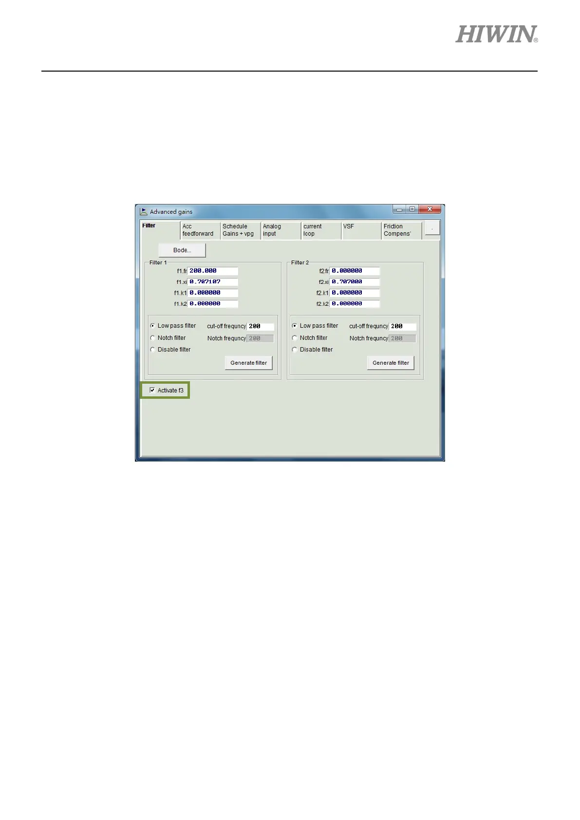
Frequency analyzer is commonly used to analyze system characteristics when configuring a filter. Click
on Bode… button in figure 6.6.1.1 to open simulation interface for Bode plot.
Figure 6.6.1.1 Filter
Low-pass filter
For how to set a low-pass filter, please refer to below.
(1) fr: fr is the cutoff frequency (Unit: Hz). For normal application, user can set cutoff frequency to
500 Hz. For other application, user can consider decreasing the value of cutoff frequency. If the
cutoff frequency is set to be too low, it may affect the controlling performance.
(2) xi: Damping ratio (Setting range: 0 to 1)
(3) k1: 0
(4) k2: 0
 Loading...
