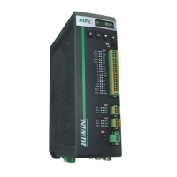
D1-N Series Servo Drive User Manual Table of Contents
Table of Contents
1. About this user manual ·············································································································· 1-1
1.1 General precautions ············································································································· 1-2
1.1.1 Risk identification ········································································································ 1-3
1.2 Safety precautions ··············································································································· 1-4
2. Specifications ·························································································································· 2-1
2.1 Safety certificates and model explanations ················································································ 2-2
2.1.1 Safety certificates ······································································································· 2-2
2.1.2 Nameplate information ································································································· 2-3
2.1.3 Model explanation ······································································································· 2-4
2.2 Servo drive specification ······································································································· 2-5
2.2.1 Basic specification ······································································································ 2-5
2.2.2 Dimensions ··············································································································· 2-9
2.3 Installation ······················································································································· 2-11
2.4 System requirements ········································································································· 2-12
3. Operation principles ·················································································································· 3-1
3.1 Operation mode ·················································································································· 3-2
3.1.1 Position mode ············································································································ 3-2
3.1.2 Velocity mode ············································································································ 3-3
3.1.3 Force/torque mode ······································································································ 3-3
3.1.4 Stand-alone mode ······································································································ 3-3
3.2 Encoder types ···················································································································· 3-3
3.3 Encoder signal output ··········································································································· 3-5
3.4 Path planning ····················································································································· 3-6
3.5 Servo loops and servo gains ·································································································· 3-8
3.6 Gain margin and phase margin ······························································································· 3-9
3.6.1 Nyquist plot ··············································································································· 3-9
3.6.2 Bode plot ················································································································ 3-11
3.7 Move and settling ·············································································································· 3-12
3.8 Error compensation ············································································································ 3-13
3.9 Velocity ripple ··················································································································· 3-14
3.10 Enabling ························································································································ 3-15
3.11 Basic physical quantities ··································································································· 3-16
4. Wiring ···································································································································· 4-1
4.1 System configuration and wiring ····························································································· 4-2
4.1.1 System connection ······································································································ 4-2
4.1.2 Connector specifications ······························································································ 4-5
4.2 Main power (X1) ·················································································································· 4-7
4.3 Regenerative resistor and DC link (X2) ··················································································· 4-10
4.4 Motor power (X3)··············································································································· 4-13
4.5 Control power and brake (X4) ······························································································ 4-14
4.6 USB communication (X5) ···································································································· 4-15
4.7 Control signals (X6) ··········································································································· 4-15
4.7.1 Digital command ······································································································· 4-17
4.7.2 Programmable I/O ···································································································· 4-18
4.7.3 Encoder output········································································································· 4-20
4.7.4 PT signal output ······································································································· 4-21
4.7.5 Analog command ······································································································ 4-21
4.8 Safety function (X7, X8) ······································································································ 4-22
4.9 Motor temperature detection (X9) ·························································································· 4-28
4.10 Encoder (X10, X11, X12) ··································································································· 4-28
4.11 EtherCAT/Modbus communication (X13) ·············································································· 4-30
4.12 Accessories of D1-N servo drive ························································································· 4-31

 Loading...