D1-N Series Servo Drive User Manual Modbus Communication
14-2 HIWIN MIKROSYSTEM Corp.
14.1 Modbus communication specification
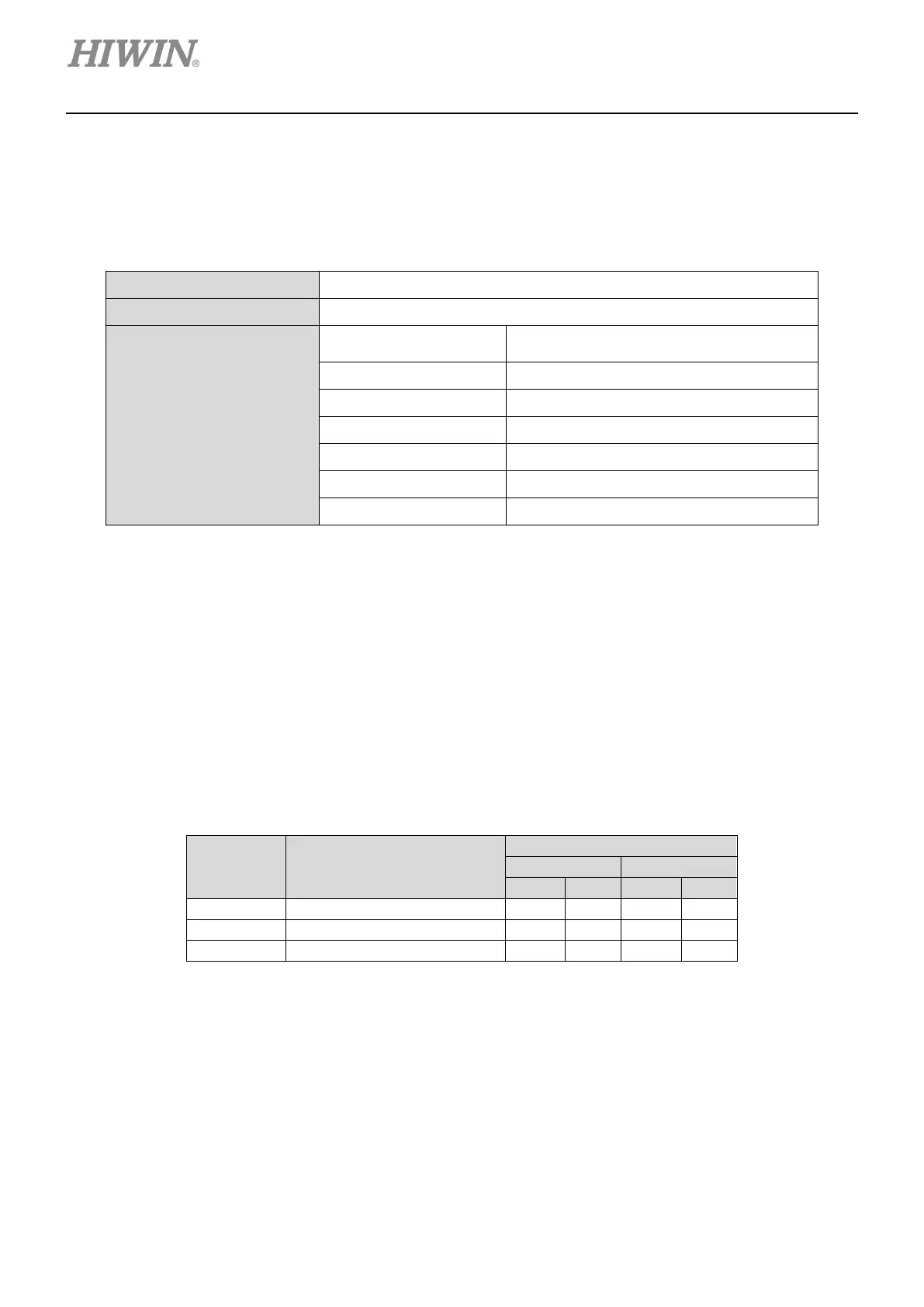
The Modbus communication specification of D1-N servo drives is listed in table 14.1.1.
Table14.1.1
Interface RS-485 2W-cabling
Communication Cycle Asynchronous (Half-duplex)
Communication Parameters
Baud Rate
2,400, 4,800, 9,600 (default), 14,400,
19,200, 38,400 bps
Communication Protocol RTU (default), ASCII
Data Length
(Note1)
8 bits (default), 7 bits
Parity Even (default), odd, none
Start bit 1 bit
Stop bit
(Note 2)
1 bit (default), 2 bits
Station Number 1 ~ 247
Note:
(1) The data length of RTU communication protocol is 8 bits. The data length of ASCII communication protocol is 7
bits.
(2) The stop bits for odd parity and even parity must be 1 bit. The stop bit for none parity must be 2 bits.
14.2 Function codes
D1-N series drives provide three types of Modbus function codes.
Table14.2.1
Function
Code
Definition
Write multiple registers.
Note:
The message length of exception response is 5 bytes.
(1) Read holding registers (03h)
This function is used to read the contents of the contiguous blocks of holding registers. The content
of each register is divided into 8 high bits and 8 low bits. 125 registers at most can be read at the
same time.

 Loading...