D1-N Series Servo Drive User Manual Servo Drive Configuration
HIWIN MIKROSYSTEM Corp. 5-39
5.4 I/O setting
5.4.1 Digital inputs
Click on on the toolbar to open I/O center. The servo drive supports 11 digital inputs (I1 to I10 and
OT). Digital inputs I1 to I10 locate on connector X6. OT locates on connector X9 for motor over
temperature.
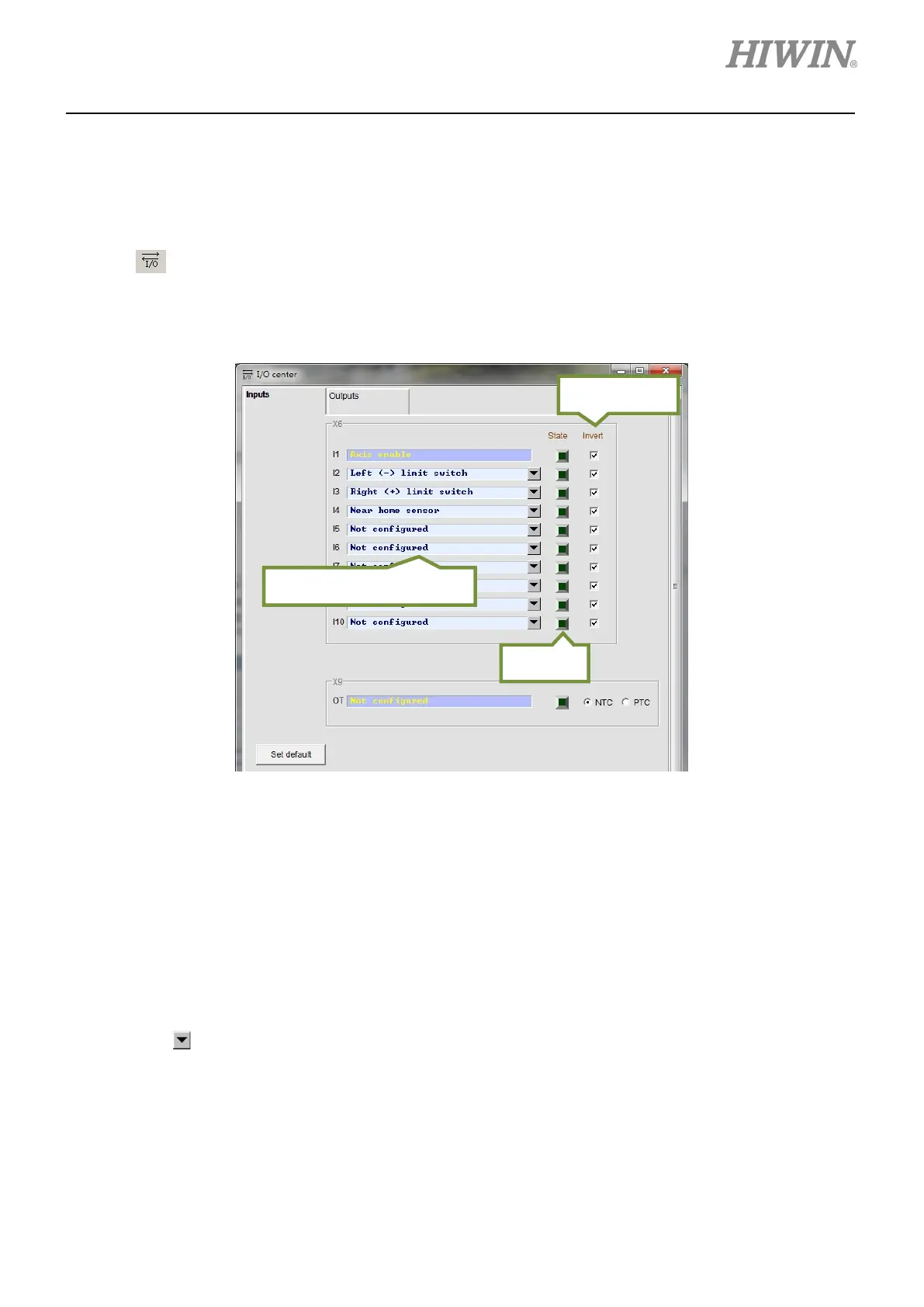
Figure 5.4.1.1
(1) Indicator
If the indicator becomes green, it means the set function is activated. If not, it means the function is
not activated.
(2) Logic setting
If Invert is selected, the trigger condition is inverted.
(3) Selection for input function
Click on
, the drop-down list shown in figure 5.4.1.2 will appear.
Selection for input function
 Loading...
