D1-N Series Servo Drive User Manual Servo Drive Configuration
5-40 HIWIN MIKROSYSTEM Corp.
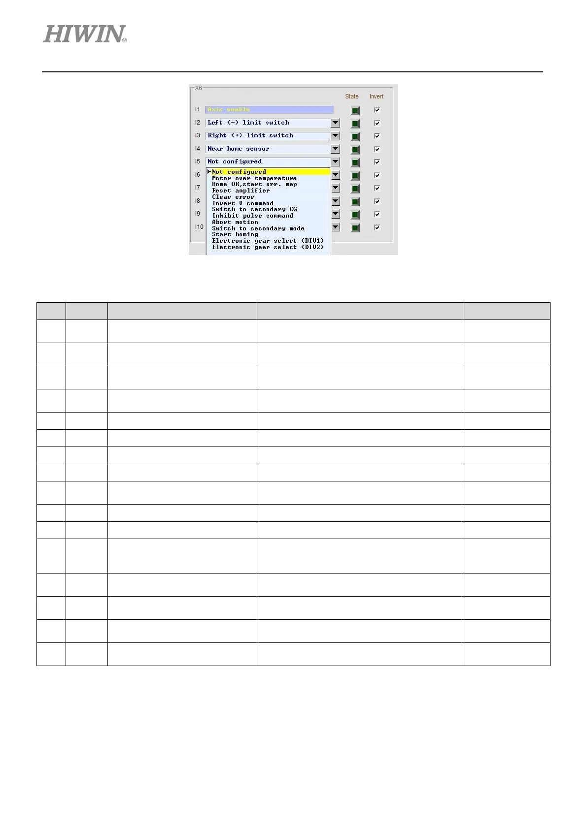
Figure 5.4.1.2
Table 5.4.1.1 Input functions
No. Abbr. Input Function Description Trigger Method
1 SVN Axis enable
Enable or disable axis.
Digital input I1 (Cannot be changed)
Level triggered
2 LL Left limit switch
Left hardware limit
Digital input I2 (Default)
Level triggered
3 RL Right limit switch
Right hardware limit
Digital input I3 (Default)
Level triggered
4 MOT Motor over temperature
Motor over temperature detection
Digital input OT (Cannot be changed)
Level triggered
5 MAP Home ok, start err. map Homing completion command from controller Edge triggered
6 RST Reset amplifier Reset the servo drive. Edge triggered
7 DOG Near home sensor Near home sensor Level triggered
8 CE Clear error Clear error. Edge triggered
9 INVC Invert V command
Invert analog command in velocity mode or
force/torque mode.
Level triggered
10 GNS Switch to secondary CG Switch to second servo gain. Level triggered
11 INH Inhibit pulse command Inhibit pulse command Level triggered
12 EMG Abort motion
When this signal is received, the motor stops
according to the emergency stop procedure.
Level triggered
13 MOD Switch to secondary mode
Switch from first operation mode to second
operation mode.
Level triggered
14 HOM Start homing
Activate the built-in homing procedure in the
servo drive.
Edge triggered
15 DIV1 Electronic gear select (DIV1)
Electronic gear ratio selection for position
mode
Level triggered
16 DIV2 Electronic gear select (DIV2)
Electronic gear ratio selection for position
mode
Level triggered
 Loading...
