D1-N Series Servo Drive User Manual Tuning
6-34 HIWIN MIKROSYSTEM Corp.
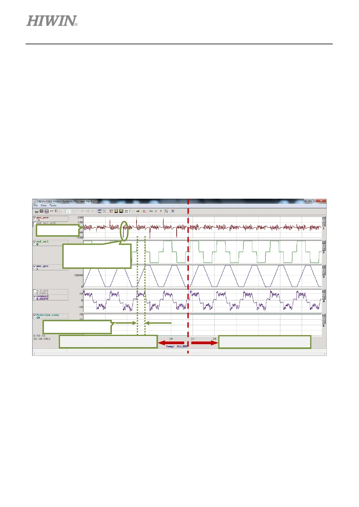
For how to apply friction compensation, please refer to the instructions below.
Step 1: Click on Set scope… button to show Scope window.
Step 2: Set friction compensation in figure 6.6.7.1 to 0.
Step 3: Set Dwell time to 500 ms.
Step 4: Set desired speed and perform point-to-point (P2P) motion. Observe position error in Scope
window. It is suggested to apply friction compensation if the positon error is greater when the
motor starts to move, as the left part of figure 6.6.7.2.
Step 5: Observe command current when the motor is moving at constant speed and calculate its
average value. As figure 6.6.7.2, the average value of command current is 20.
Step 6: Input the average value from step 5 into the field of friction compensation.
Step 7: Observe if the position error when the motor starts to move has decreased, as the right part of
figure 6.6.7.2. The position error has decreased after friction compensation is applied.
Figure 6.6.7.2 Friction compensation
6.7 Loop constructor
In Loop constructor, users are able to check the stability of control system. Loop constructor supports
spectrum analysis tools, such as Nyquist plot, Nichols plot and Bode plot and allows users to adjust filters
and gains (vpg, vig, ppg and CG). Users can directly observe the frequency response of control system
and adjust parameters in Loop constructor. To open Loop constructor window, click on Tools on the
menu bar and select Loop constructor from the submenu, as figure 6.7.1. The interface of Loop
constructor is shown in figure 6.7.2.
Position error is greater
as the motor starts to
Friction compensation is not applied.
Friction compensation is applied.
 Loading...
