D1-N Series Servo Drive User Manual Operation Principles
3-8 HIWIN MIKROSYSTEM Corp.
3.5 Servo loops and servo gains
Servo loops
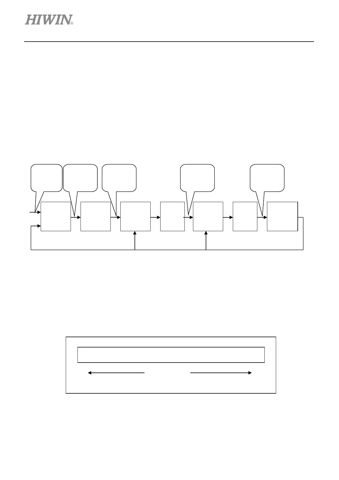
D1-N servo drive includes three servo loops, current loop, velocity loop and position loop, to control
motor. The servo loops of D1-N servo drive are shown in figure 3.5.1. In position mode, all loops are
handled by the servo drive. In velocity mode, velocity loop and current loop are handled by the servo
drive. In torque/force mode, only current loop is handled by the servo drive. Current loop receives
voltage command from controller and controls motor commutation. For easy operation, the servo
loops of D1-N servo drive can be set and adjusted by one common gain (CG).
Figure 3.5.1
Servo gains
D1-N servo drive uses one high-speed digital signal processor (DSP) to control motor. Normally if
servo loops are controlled via digital method, users need to adjust several servo gains. But for easy
operation, D1-N servo drive provides one common gain (CG) for users to adjust all servo gains at the
same time.
Figure 3.5.2
…………………………………
……………………………………
Gain
Loop
Loop
Loop
Encoder
Position
Position
Velocity
Current
Output
 Loading...
