D1-N Series Servo Drive User Manual Servo Drive Configuration
HIWIN MIKROSYSTEM Corp. 5-27
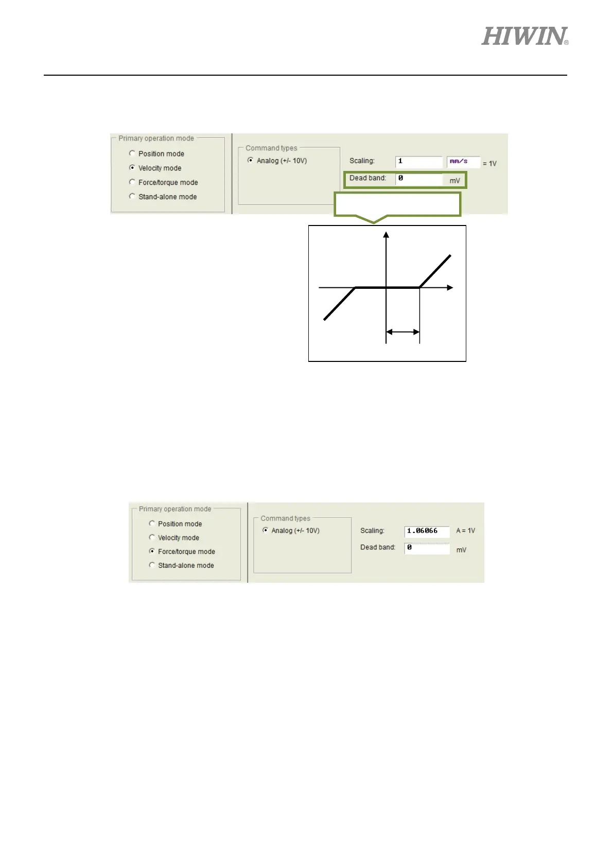
setting page in figure 5.2.4.3. Set 1 V equals what velocity in mm/s (linear motor) or rpm (rotary
motor). If a negative value is set for Scaling, the motor moves in reverse direction.
Figure 5.2.4.3
(3) Force/torque mode
Another operation mode which can be used with controller sending analog commands is
force/torque mode. The ratio (scaling) between analog command and current can be set in the
setting page in figure 5.2.4.4. Set 1 V equals what current in ampere (A). If a negative value is set for
Scaling, the motor moves in reverse direction.
Figure 5.2.4.4
(4) Stand-alone mode
If users would like the servo drive to be tested alone or operated without controller, please select
stand-alone mode. In this mode, all loops are controlled by the servo drive.
5.2.5 Setting servo drive
The setting page for setting the servo drive is shown in figure 5.2.5.1. After the settings described in
sections 5.2.1 to 5.2.4 are completed, the last step is to set the input power of the servo drive. Select main
power value according to the actual input voltage.
 Loading...
