D1-N Series Servo Drive User Manual Wiring
4-14 HIWIN MIKROSYSTEM Corp.
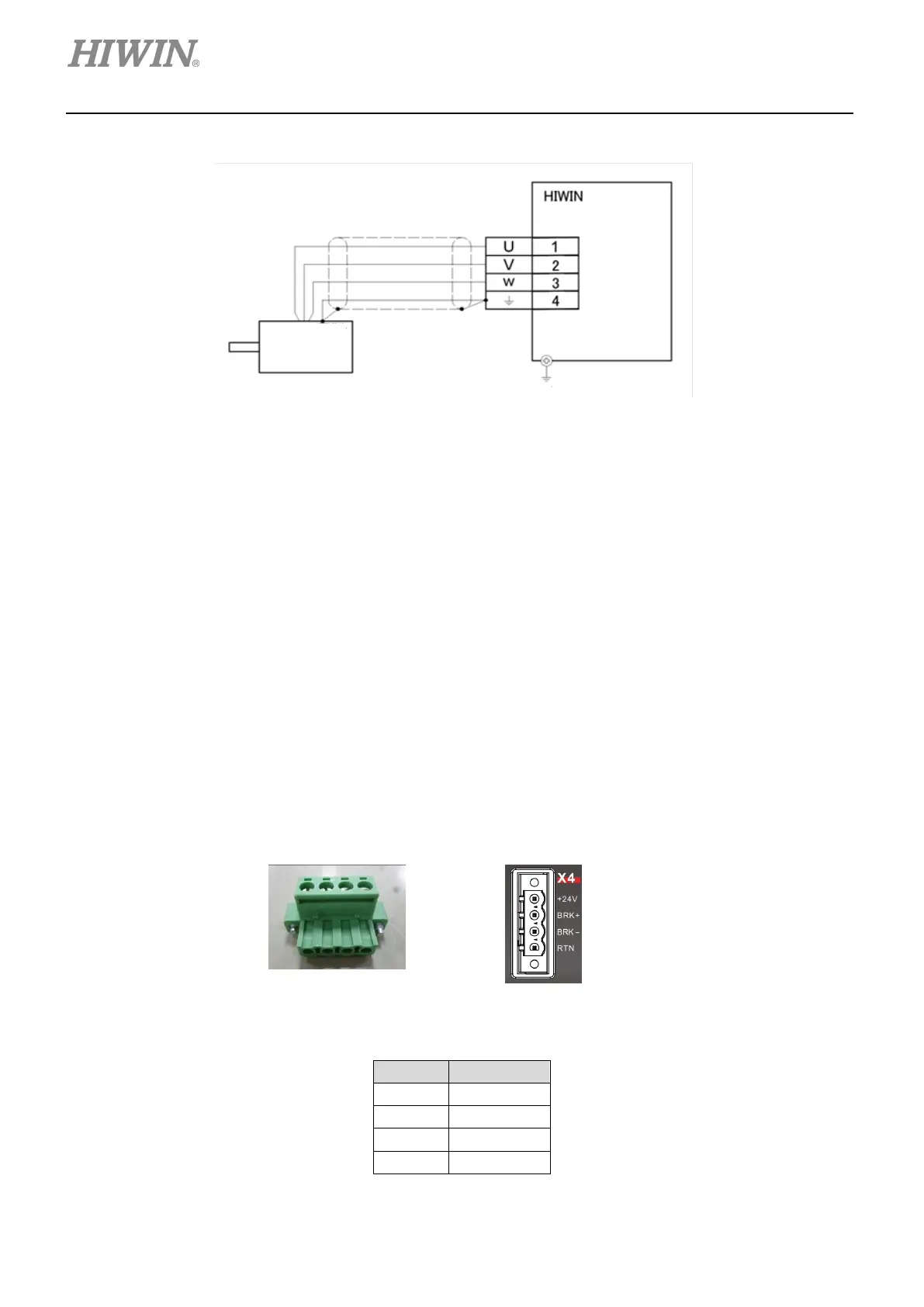
(2) Wiring example
Figure 4.4.3
4.5 Control power and brake (X4)
For connecting 24 Vdc control power and brake, please refer to figure 4.1.1.2. When no brake is used,
+24 V should be connected to pin +24 V (Pin 1) and 0 V should be connected to pin RTN (Pin 4). When
brake is used, pins BRK+ and BRK- should be connected to relay. After brake signal is output, dynamic
brake or electromagnetic brake will be activated. Pins BRK+ and BRK- are open-drain output pins. (Max.
voltage: 40 V; Max. current: 1 A) The default output for brake signal is O4. For setting output function,
please refer to section 5.4.2.
Note:
If brake is connected and “boot mode” or “COM error” occurs after motor is enabled, it means the +24 V input current
could be insufficient for control circuit to be normally operated. Ensure input current is sufficient.
(1) Connector
Figure 4.5.1 Connector: MSTB 2, 5/X-STF
Table 4.5.1
1 +24V
4 RTN
 Loading...
