D1-N Series Servo Drive User Manual Tuning
6-40 HIWIN MIKROSYSTEM Corp.
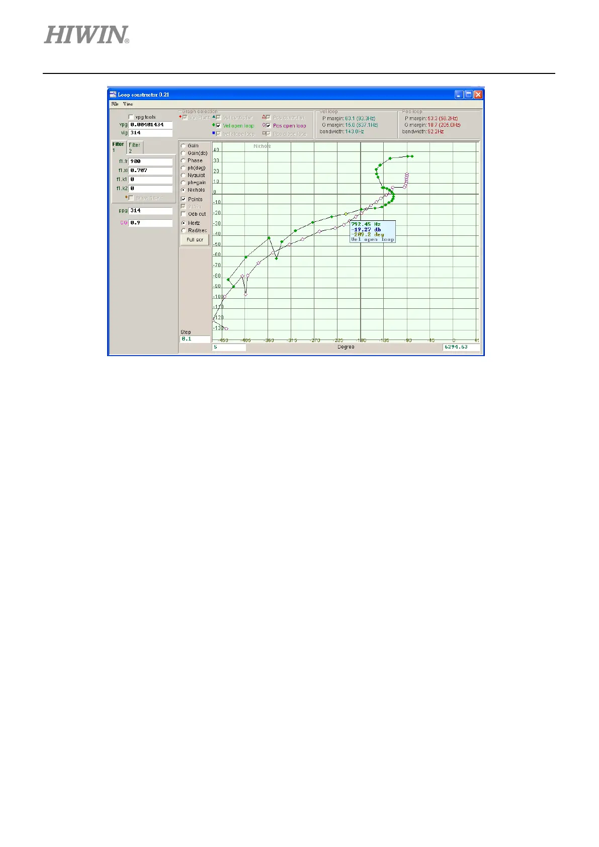
Figure 6.7.2.4.1 Nichols plots of velocity open loop and position open loop
6.7.3 Filter
Two filters are provided for the control loop of the servo drive to deal with high-frequency noise, machine
vibration or insufficient structural stiffness.
6.7.3.1 Low-pass filter
Low-pass filter in control loop is used to suppress high-frequency noise or machine vibration. Figure
6.7.3.1.1 shows the Bode plot of low-pass filter. Modify the parameters of filter (fr and xi) to simulate how
the filter affects the frequency response of the control system.
(1) fr: fr is the cutoff frequency (Unit: Hz). For normal applications, users can set cutoff frequency to 500
Hz. For other applications, users can consider decreasing the value of cutoff frequency. If the cutoff
frequency is set to be too low, it may affect the controlling performance.
(2) xi: Damping ratio (Setting range: 0 to 1)
(3) k1: Low-pass filter = 0
(4) k2: Low-pass filter = 0

 Loading...