D1-N Series Servo Drive User Manual Tuning
HIWIN MIKROSYSTEM Corp. 6-41
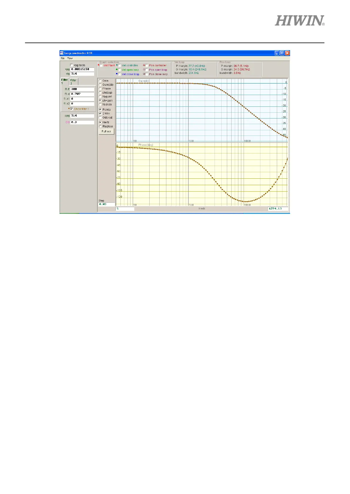
Figure 6.7.3.1.1 Low-pass filter
6.7.3.2 Notch filter
When resonance frequency occurs and cannot be fixed by modification of mechanism or improvement of
design, users can consider using notch filter. Figure 6.7.3.2.1 shows the Bode plot of notch filter. Modify
the parameters of filter (fr and xi) to simulate how the filter affects the frequency response of the control
system.
(1) fr: Cutoff frequency (Unit: Hz)
(2) xi: Damping ratio (Setting range: 0 to 1)
When the value is close to 0, the filtering frequency band will be narrower; when the value is close to
1, the filtering frequency band will be wider.
(3) k1: Notch filter = 0
(4) k2: Notch filter = 1
 Loading...
