EasyManua.ls Logo

Hiwin D1-N Series User Manual

Hiwin D1-N Series
283 pages
To Next Page IconTo Next Page
To Previous Page IconTo Previous Page
Page #270 background imageLoading...
Page #270 background image
D1-N Series Servo Drive User Manual Modbus Communication
14-6 HIWIN MIKROSYSTEM Corp.
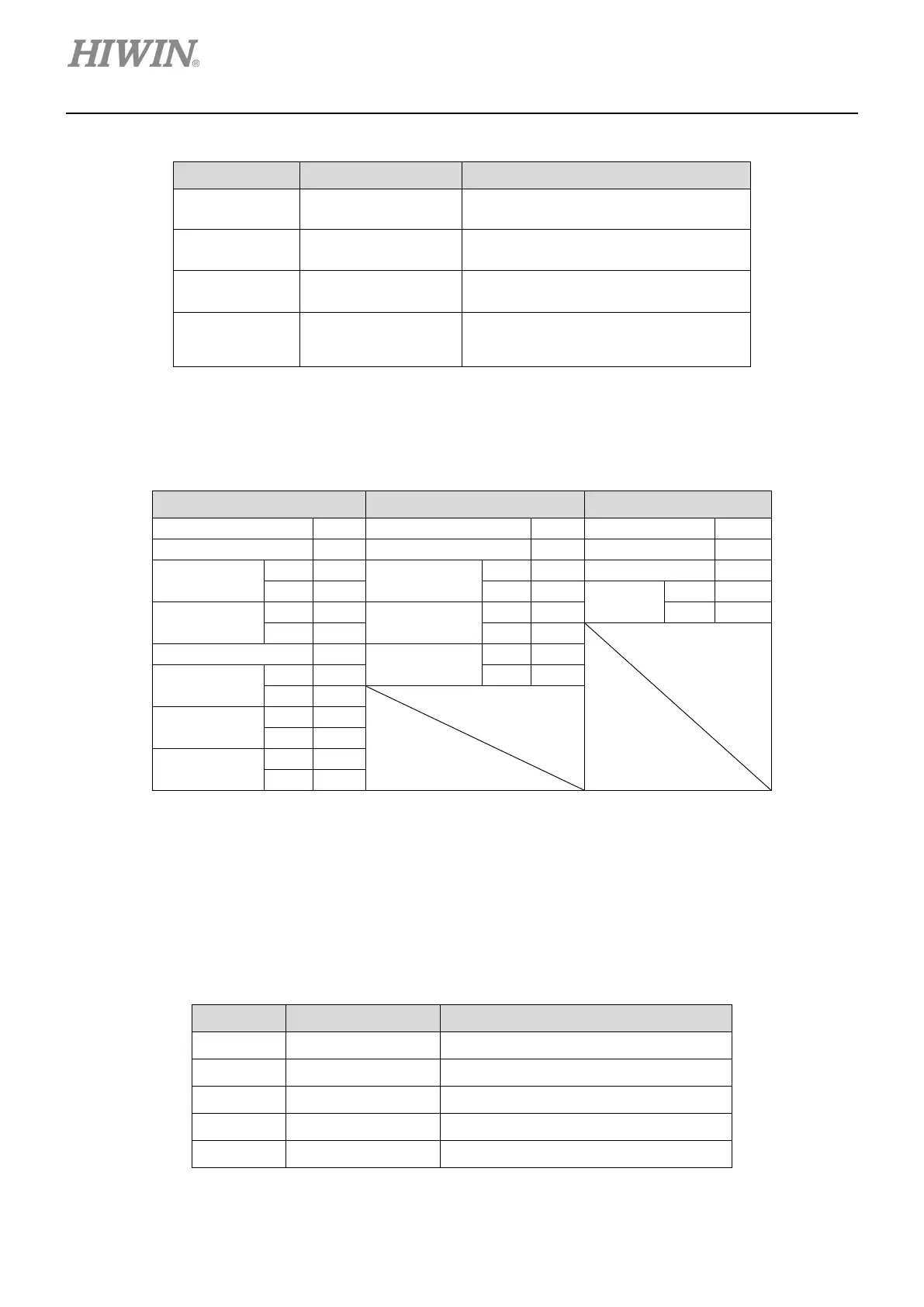
MD17UE01-1906
Table14.2.9
Exception Code Definition Description
01h Illegal function The function code is not supported.
02h Illegal data address Try to read an illegal register.
03h Illegal data value The number of registers is over 123.
04h Servo device failure
The request contains incomplete data.
For instance, the controller only
requests 16 bits of a 32-bit parameter.
Table 14.2.10 is the example of writing two registers. The starting address is 0x0001. The values are
00 0Ah and 01 02h.
Table14.2.10
Command Response Error
Slave address
01h
Slave address
01h
Slave address
01h
Function code
10h
Function code
10h
Function code
90h
Starting
address
Hi
00h
Starting
address
Hi
00h
Exception code
02h
Lo
01h
Lo
01h
CRC
Lo
CDh
Register
number
Hi
00h
Register
number
Hi
00h
Hi
C1h
Lo
02h
Lo
02h
Byte count
04h
CRC
Lo
10h
Register
0x0001
Hi
00h
Hi
08h
Lo
0Ah
Register
0x0002
Hi
01h
Lo
02h
CRC
Lo
92h
Hi
30h
14.3 Modbus object
The data types of Modbus objects are listed in table 14.3.1.
Table14.3.1
Code Data Type Data Range
INT16 Signed 16 bit -32,768~+32,767
INT32 Signed 32 bit -2,147,483,648~+2,147,483,647
UINT16 Unsigned 16 bit 0~65,535
UINT32 Unsigned 32 bit 0~4,294,967,295
REAL32 Float 32 bit -

Table of Contents

Other manuals for Hiwin D1-N Series

Questions and Answers:

Hiwin D1-N Series Specifications

General IconGeneral
BrandHiwin
ModelD1-N Series
CategoryAmplifier
LanguageEnglish

Summary

About this user manual

General precautions

Follow installation and operating instructions for safe product use.

Safety precautions

Important safety information including warnings, attention, prohibitions, and requirements.

Risk identification

Identifies potential hazards and risks associated with product operation and usage.

Specifications

Installation

Outlines procedures and requirements for installing the servo drive.

Wiring

System configuration and wiring

Provides an overview of system configuration and electrical wiring diagrams.

Main power (X1)

Details the connection and wiring for the main AC power input.

Motor power (X3)

Describes the wiring for connecting the motor power cable.

Control signals (X6)

Explains the wiring and functions of various control signal inputs and outputs.

Safety function (X7, X8)

Describes the wiring and implementation of safety functions like STO.

Servo drive configuration

Installation and communication

Covers the installation of Lightening software and establishing communication.

Configuration center

Explains how to use the Configuration center for setting motor, encoder, and operation parameters.

Auto phase center

Details the process and precautions for auto phase initialization.

Homing

Covers the setup and procedures for motor homing.

Save parameters to Flash and set to factory default

Explains how to save configurations and restore factory default settings.

Setting operation mode via Lightening

Guides users on how to set the servo drive's operation mode using the Lightening software.

Tuning

Advanced gain tuning

Explains how to adjust gains and parameters for improved servo control performance.

Protection function

Motion protection

Sets limits for speed, acceleration, and deceleration to protect the motor.

Position and velocity error protection

Configures limits and warnings for position and velocity errors.

Over temperature protection

Explains protection mechanisms for motor and servo drive over-temperature conditions.

Overvoltage protection

Describes how to protect the servo drive from overvoltage using regenerative resistors.

Errors and warnings

Error messages and warning messages

Lists all possible error and warning messages and their meanings.

Troubleshooting

Provides guidance on diagnosing and resolving issues based on status indicators and error codes.

Enabling motor

Updating firmware and loading PDL

Motor power cable shielding and grounding