D1-N Series Servo Drive User Manual Servo Drive Configuration
HIWIN MIKROSYSTEM Corp. 5-41
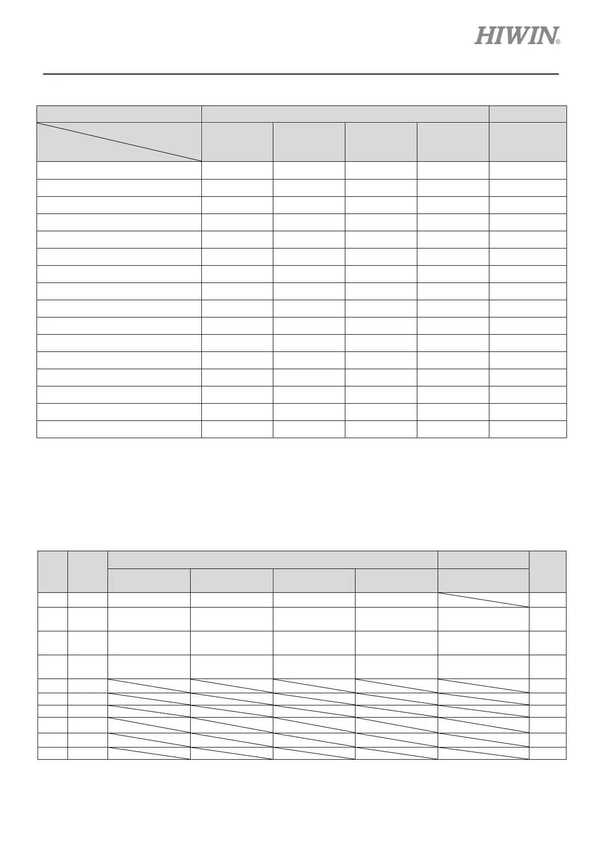
Table 5.4.1.2 Supported input functions in each operation mode
Not CoE Model CoE Model
Operation Mode
Input Function
Position
Mode
Velocity
Mode
Force/torque
Mode
Stand-alone
Mode
Stand-alone
Mode
Axis enable O O O O ∆
Left limit switch V - - V O
Right limit switch V - - V O
Motor over temperature O O O O O
Home ok, start err. map V V V V V
Reset amplifier V V V V V
Near home sensor V V V V O
Clear error V V V V -
Invert V command - V V - -
Switch to secondary CG V V V V -
Inhibit pulse command V - - - -
Abort motion - - - V -
Switch to secondary mode V V V V -
Start homing V V V V -
Electronic gear select (DIV1) V - - - -
Electronic gear select (DIV2) V - - - -
Note:
(1) V means the input function is supported in the operation mode and can be assigned to I2 to I10.
(2) O means the input function is supported in the operation mode, but cannot be assigned by users.
(3) ∆ means for D1-N CoE model, its digital input I1 can only be set for “Axis enable” or “Not configured”.
Table 5.4.1.3 Default input functions of digital inputs
Pin Signal
Not CoE Model CoE Model
Invert
8 I2
Yes
9 I3
Yes
10 I4
Yes
14 I8
Yes
 Loading...
