D1-N Series Servo Drive User Manual Servo Drive Configuration
5-42 HIWIN MIKROSYSTEM Corp.
Input Function Clear Error Applicable Operation Mode Pos Vel Trq Std
Function
Clear error.
Description
When the input set for clearing error is from OFF to ON, error will be cleared.
After error is cleared, Software Enabled will be ON.
Input Function Start Homing Applicable Operation Mode Pos Vel Trq Std
Function
Homing
Description
When the input set for starting homing is from OFF to ON, homing will be started according to the
method set in Application center.
Input Function Abort Motion Applicable Operation Mode Pos Vel Trq Std
Function
In stand-alone mode, when the input set for aborting motion is ON, the motor will decelerate at the
speed set in Dec. kill to a stop. Dec. kill can be set in Performance center.
Description
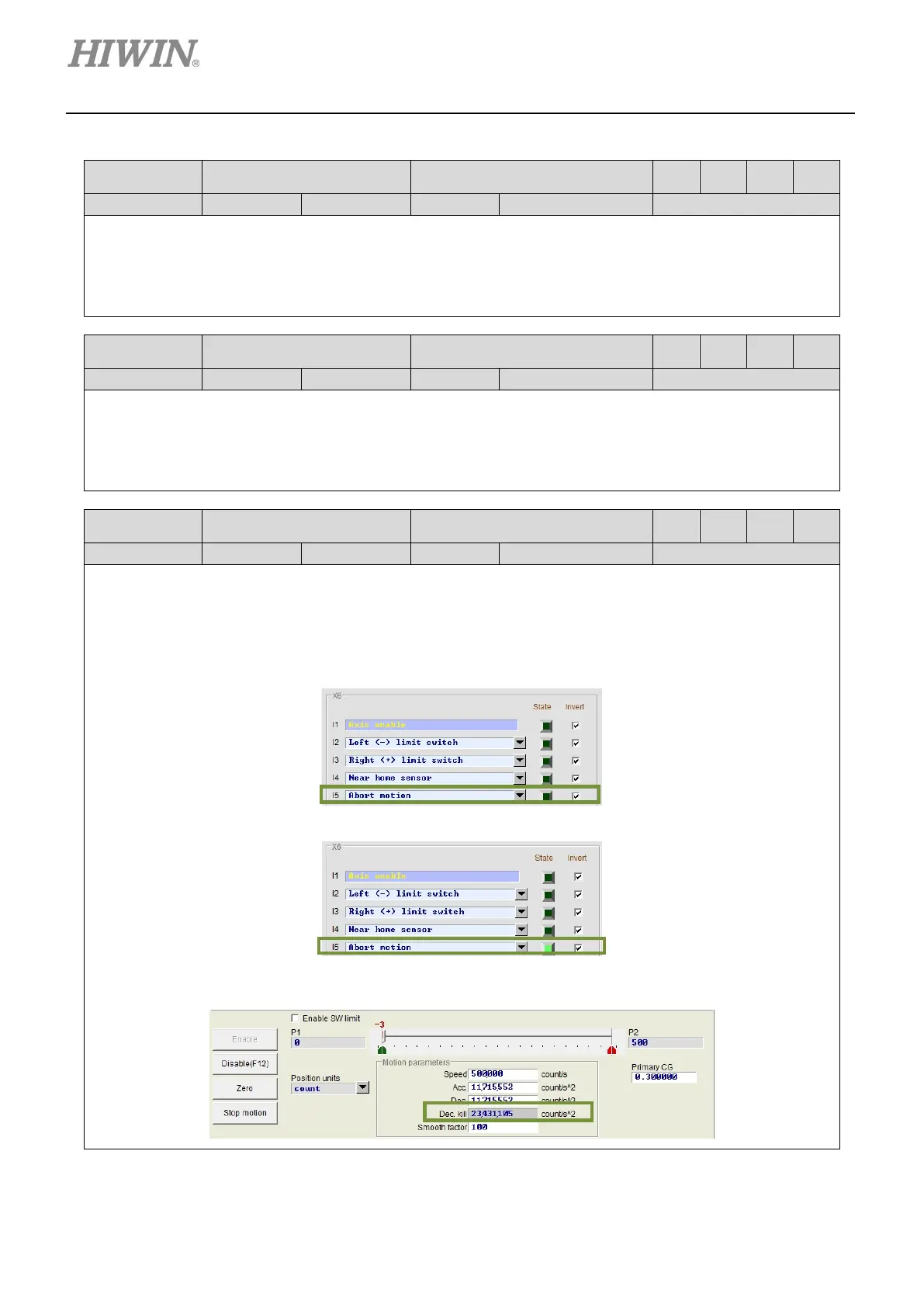
Set one input for aborting motion in I/O center. Use external signal to decelerate the motor at the speed
set in Dec. kill to a stop. In the figure below, I5 is set for aborting motion.
After external signal is input, the motor decelerates at the speed set in Dec. kill to a stop.
When State indicator becomes green, the servo drive decelerates the motor at the speed set in Dec.
kill to a stop.

 Loading...