D1-N Series Servo Drive User Manual Wiring
4-16 HIWIN MIKROSYSTEM Corp.
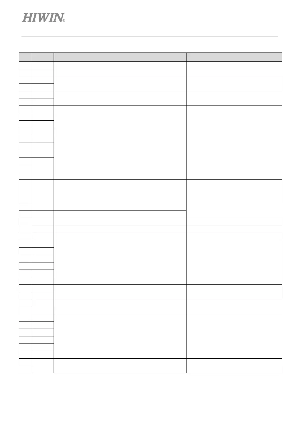
Table 4.7.1 Pin definition of connector for control signals
Pin Signal Function Note
DC 12 V ~ DC 24 V must be provided. -
Differential signal input (4 MHz)
Channel 1: Pulse, CW, A phase
-
Differential signal input (4 MHz)
Channel 2: Dir, CCW, B phase
-
6 CCW-
Programmable
General input signals
9 I3
12 I6
17 COM Common point for general input signals (I1 ~ I10)
For NPN type: 12 V ~ 24 V must be
provided.
For PNP type: Connect to ground
Analog command input (Positive)
Default velocity/torque analog command
(+/-10 V)
Analog command input (Negative)
20 DSF+ Disable safety function (Positive) -
Ground reference for input and output signals
23 O1+
General output signals Programmable
Output for position trigger -
- -
Feedback pulse output (Buffered encoder or emulated
encoder)
-
37 Z
Z phase open-collector output
40 DSF- Disable safety function (Negative) -
 Loading...
