EasyManuals Logo

Hiwin D1-N Series User Manual

Hiwin D1-N Series
283 pages
To Next Page IconTo Next Page
To Previous Page IconTo Previous Page
Page #69 background imageLoading...
Page #69 background image
D1-N Series Servo Drive User Manual Wiring
HIWIN MIKROSYSTEM Corp. 4-29
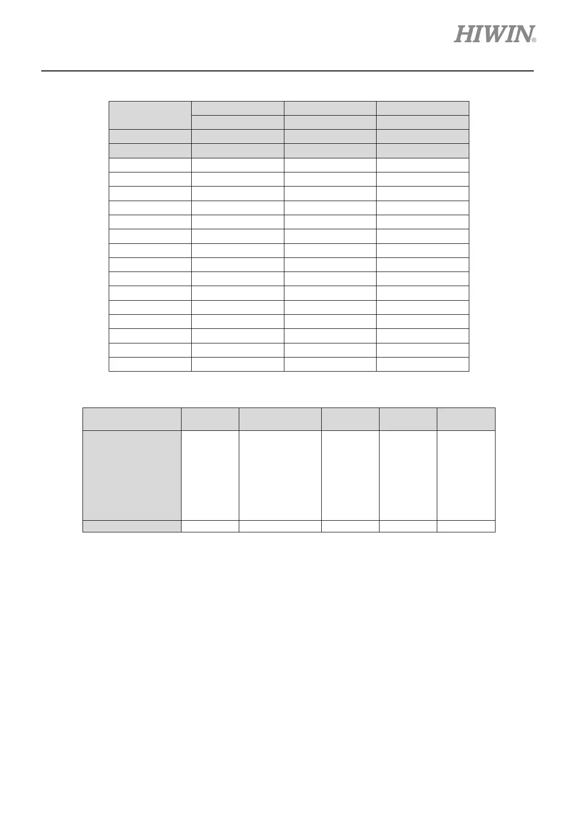
MD17UE01-1906
Table 4.10.1
Connector Type
X10
X11
X12
Female Female Male
Description
Digital/Hall Sensor
Analog/Serial
Resolver
Pin
Signal
Signal
Signal
1
A+
SIN+
SIN1+
2
B+
COS+
COS1+
3
Z+
Index+
SIN2+
4
FLT
+9 Vdc
AGND
5
+5 Vdc
+5 Vdc
+5 Vdc
6
A-
SIN-
SIN1-
7
B-
COS-
COS1-
8
Z-
Index-
SIN2-
9
Hall A
n.c.
COS2+
10
Hall B
n.c.
COS2-
11
Hall C
DX+ (Data)
REF+
12 n.c. DX- (Data) REF-
13
DSL+
(Note 4)
CLK+ (Clock)
Index+
14
DSL-
(Note 4)
CLK- (Clock)
Index-
15 GND GND GND
Table 4.10.2
Encoder Type
(Note 4)
EnDat2.1
EnDat2.2/Nikon
/BiSS/SSI
Hiperface
DSL
Hiperface T-code
Signal
+5 Vdc
GND
DX+
DX-
SIN+
SIN-
COS+
COS-
+5 Vdc
GND
DX+
DX-
CLK+
CLK-
DSL+
DSL-
+9 Vdc
GND
DX+
DX-
SIN+
SIN-
COS+
COS-
+5 Vdc
GND
DX+
DX-
Connector
X11
X11
X10
X11
X11
Note:
(1) If analog/serial encoder and digital Hall sensor are used, connectors X10 and X11 must both be connected.
(2) To avoid EMC malfunction, encoder cable must be shielded. The shield of the encoder cable must contact the
shell of the connector.
(3) FLT signal on connector X10 can only be used with encoder which supports encoder fault signal.
(4) Available on D1-N--9.

Table of Contents

Other manuals for Hiwin D1-N Series

Questions and Answers:

Question and Answer IconNeed help?

Do you have a question about the Hiwin D1-N Series and is the answer not in the manual?

Hiwin D1-N Series Specifications

General IconGeneral
BrandHiwin
ModelD1-N Series
CategoryAmplifier
LanguageEnglish