D1-N Series Servo Drive User Manual Servo Drive Configuration
5-8 HIWIN MIKROSYSTEM Corp.
: Load parameters from file (PRM file) to the servo drive RAM. If dual loop function is set,
phase initialization must be performed again after parameters are loaded.
: Save parameters from the servo drive RAM to Flash.
: Reset the servo drive.
(2) Status indicator
: The indicator is off when the servo drive is in disabling state. When the servo drive is in
enabling state the indicator will be green.
: The indicator is green for hardware enabling. If hardware enabling is not
activated first, the motor cannot be successfully enabled. For the setting method of hardware
enabling by external input, please refer to section 5.4.1 and chapter 11.
: The indicator is green for software enabling. Only when hardware and software
enablings are both activated, the motor can be successfully enabled. In Performance center, click on
Enable button to activate software enabling. Click on Disable button to deactivate software
enabling. When PC and the servo drive are not connected, the status of software enabling varies
with the status of hardware enabling. If PC and the servo drive are connected, while closing the
window, a message dialog will appear asking whether the software enabling should be activated or
not.
: The indicator is green when STO safety function is activated. Ensure dangerous
situation has been cleared before supplying 24 V for STO safety function. Connect DSF+ and DSF-
on X6 connector for one second to reset STO safety function.
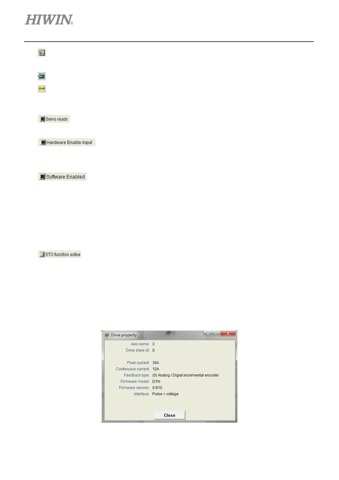
(3) Drive property
Right click on axis name and select Properties, the properties of the servo drive will be displayed as
figure 5.1.3.2.
Figure 5.1.3.2
 Loading...
