ECC800 Data Center Controller
User Manual (for ECC800-Pro)
Copyright © Huawei Technologies Co., Ltd.
Cabinet 1:
smart U space
manager
Cabinet 2:
smart U space
manager
Cabinet 3:
smart U space
manager
Cabinet 4:
smart U space
manager
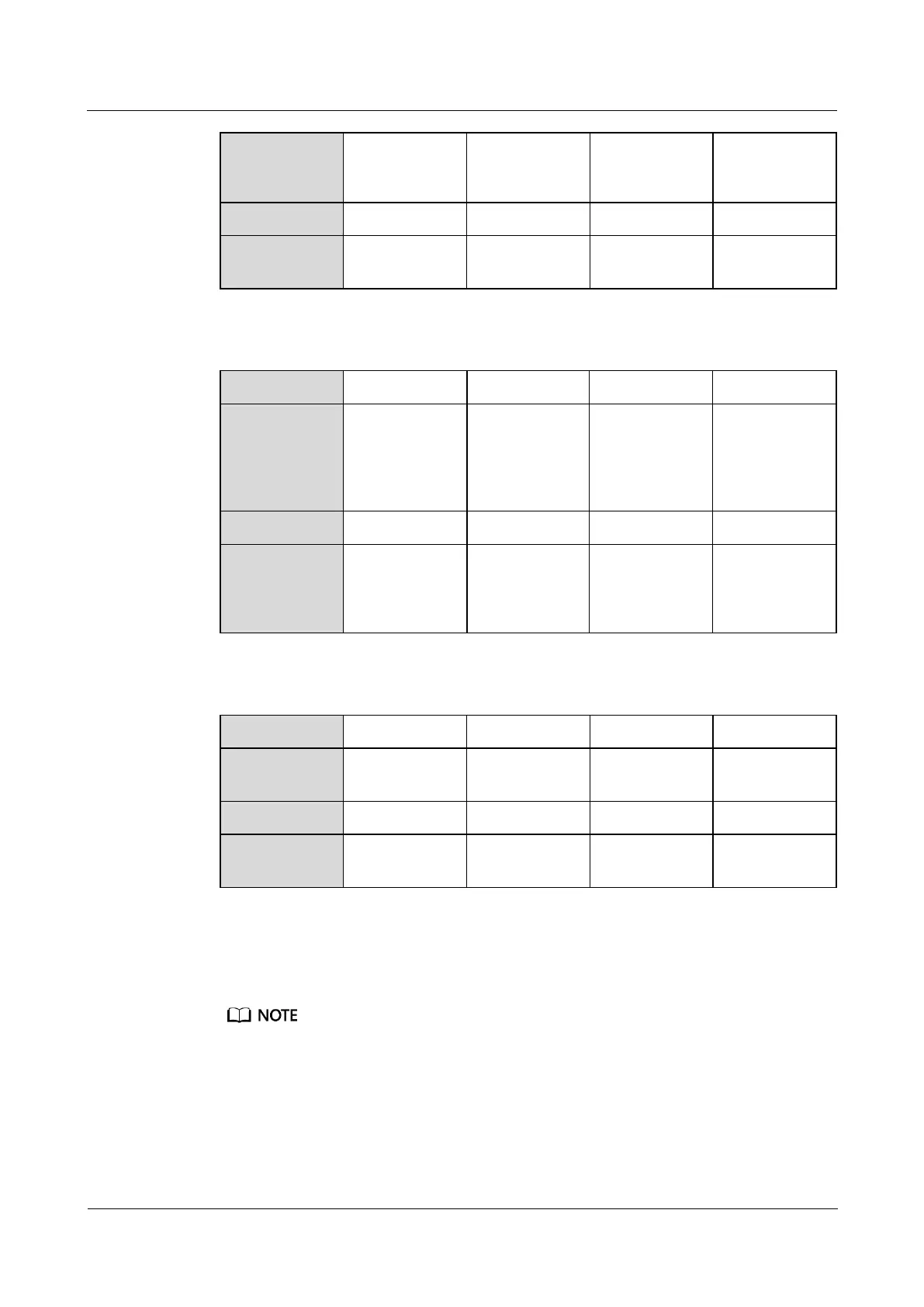
Table 6-4 Cable connection mode 3 in the scenario where one UIM maps to four cabinets
Cabinet 1:
cabinet
electronic lock
on the front
door
Cabinet 2:
cabinet
electronic lock
on the front
door
Cabinet 3:
cabinet
electronic lock
on the front
door
Cabinet 4:
cabinet
electronic lock
on the front
door
Cabinet 1:
cabinet
electronic lock
on the rear door
Cabinet 2:
cabinet
electronic lock
on the rear door
Cabinet 3:
cabinet
electronic lock
on the rear door
Cabinet 4:
cabinet
electronic lock
on the rear door
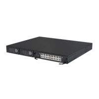
Table 6-5 Cable connection mode 4 in the scenario where one UIM maps to four cabinets
Temperature map scenario
In the scenario where T/H sensors are connected, 32 T/H sensors are connected to one
UIM.
Each COM port allows a maximum of eight T/H sensors to be cascaded.
The addresses of the T/H sensors connected to the same COM port must be different. Addresses 1 to
8 are supported. The addresses of T/H sensors connected to different COM ports can be the same. In
actual configuration, bind sensors to the corresponding cabinets in sequence.
Each cabinet can connect to only one T/H sensor, a T/H sensor is automatically bound to the cabinet
after its DIP switch is set. The LCD of the T/H sensor displays the DIP switch address.