ECC800 Data Center Controller
User Manual (for ECC800-Pro)
Copyright © Huawei Technologies Co., Ltd.
One UIM connects to 32 T/H sensors. If the smart module connects to more than 32 IT cabinets, two
UIMs are required for expansion. Each UIM must be installed in the first cabinet of the
corresponding IT cabinets, and the cable connection principles remain unchanged.
In this scenario, a UIM is not bound to the IT cabinet.
Only the T/H sensor inside the cabinet can be connected to the UIM.
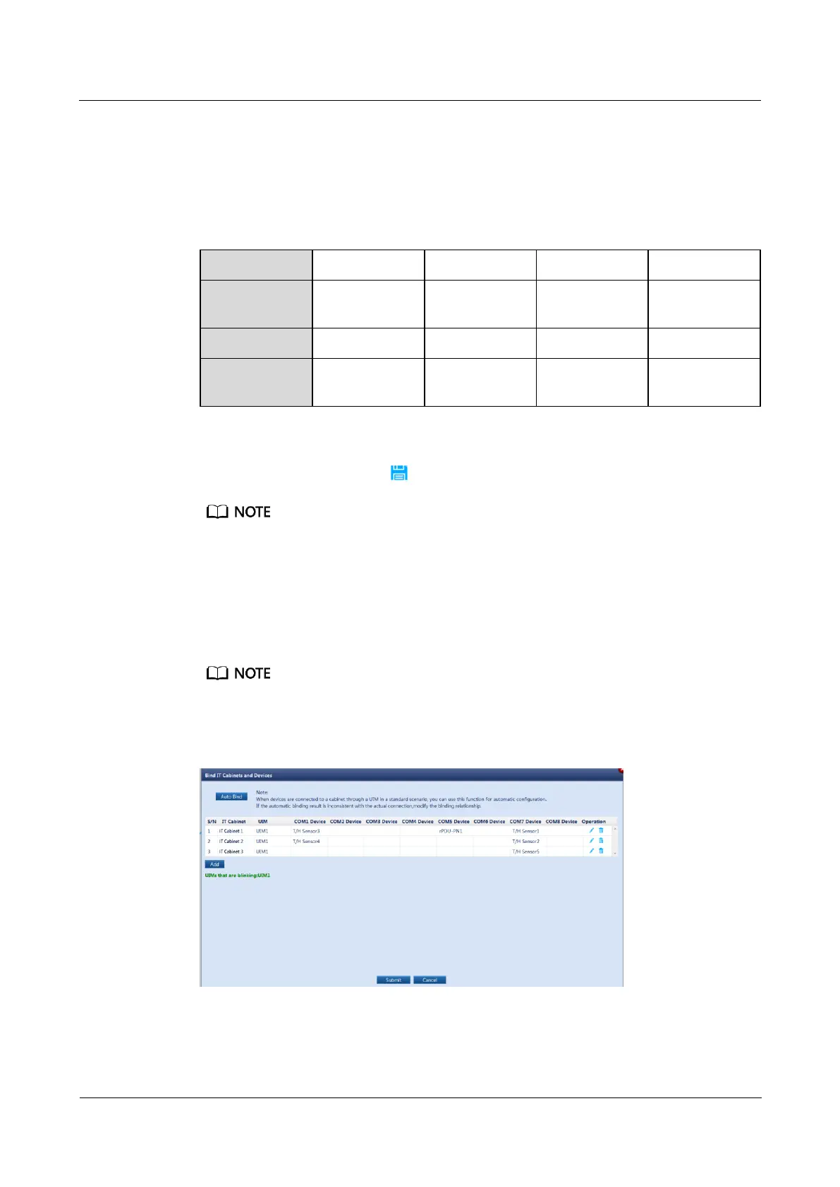
Table 6-6 Cable connection mode in a temperature map scenario
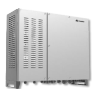
Step 5 (Optional) Click Add, set IT Cabinet, select a UIM and the devices connected to each COM
port of the UIM20A, and click in the Operation column to manually bind the devices.
If the automatic cabinet binding result is inconsistent with the actual connection or the automatic cabinet
binding function cannot be used, you need to manually bind devices.
Step 6 Click Submit.
Step 7 Hold down the BLINK button on the UIM for less than 2s. The RUN indicator on the UIM
blinks fast, and the dialog box for binding IT cabinets and devices shows the UIM that is
blinking.
You can determine the IT cabinet that houses the UIM through indicator blinking. Then, you can change
the IT cabinet name.
Figure 6-3 Device blinking