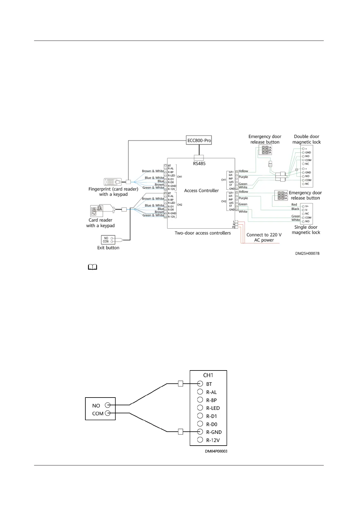
● The following gure uses the double-door access controller as an example to
illustrate the wiring method for the access control system. In this example, the
ngerprint and card reader (with a keypad) connects to the CH1 terminal on
the left of the access controller, the card reader with a keypad connects to the
CH2 terminal on the left of the access controller, the double-door magnetic
lock connects to the CH1 terminal on the right of the access controller, and
the single-door magnetic lock connects to the CH2 terminal on the right of
the access controller.
Figure 4-28 General cable connections for the access control system
● Connect the RS485 ports on the access controller and the ngerprint and card reader (with a
keypad) respectively to any two of COM1 to COM4 ports on the ECC800-Pro collector.
● Fingerprint and card reader (with a keypad) refers to the ngerprint and card reader with a
keypad or the
ngerprint and card reader.
Connecting Cables to the Exit Button
Figure 4-29 shows the cable connections to the access controller and exit button,
using the cord end terminal to crimp the cable.
Figure 4-29 Connecting cables to the exit button
iMaster NetEco
Device Installation and Commissioning Guide (Data
Center) 4 Connecting Monitoring Cables to Devices
Issue 02 (2021-05-12) Copyright © Huawei Technologies Co., Ltd. 107
 Loading...