Table 4-32 Pin mapping for the RS485 port and the COM port
RS485 Port on Fingerprint and Card Reader
with a Keypad
COM Port on ECC800-
Pro Collector
Pin Denition Pin
Pin1 485A (brown) Pin1
Pin2 485B (gray) Pin2
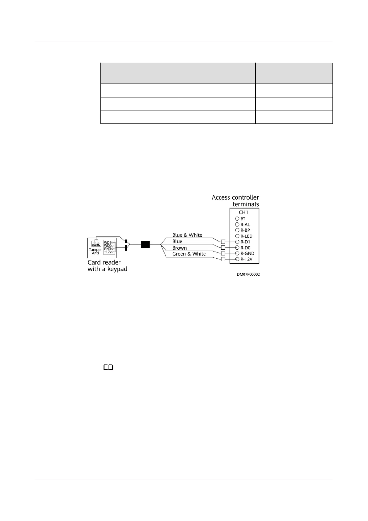
Connecting Cables to the Card Reader with a Keypad
The following
gure shows the cable connections to the access controller and card
reader with a keypad, using the cord end terminal to crimp the cable.
Figure 4-31 Connecting cables to the card reader with a keypad
Connecting Cables to the Single-Door Magnetic Lock, Double-Door
Magnetic Lock, and Emergency Door Release Button
● The double-door magnetic lock is delivered with eight cables. Connect the
cables to the double-door magnetic lock, as shown in Figure 4-32. Crimp the
cable on the access controller side using a cord end terminal.
● Figure 4-33 shows the cable connections to the access controller, single-door
magnetic lock, and emergency door release button. Crimp the cables using
cord end terminals.
● The magnetic lock is delivered with a small white terminal. Cut o the white
terminal and then use a cord end terminal for crimping.
● The cable installation sequences shown in the following gure are for reference
only. If any dierences exist between the wiring diagram and this gure, the wiring
diagram prevails.
iMaster NetEco
Device Installation and Commissioning Guide (Data
Center) 4 Connecting Monitoring Cables to Devices
Issue 02 (2021-05-12) Copyright © Huawei Technologies Co., Ltd. 109
 Loading...