7 Configuration
160
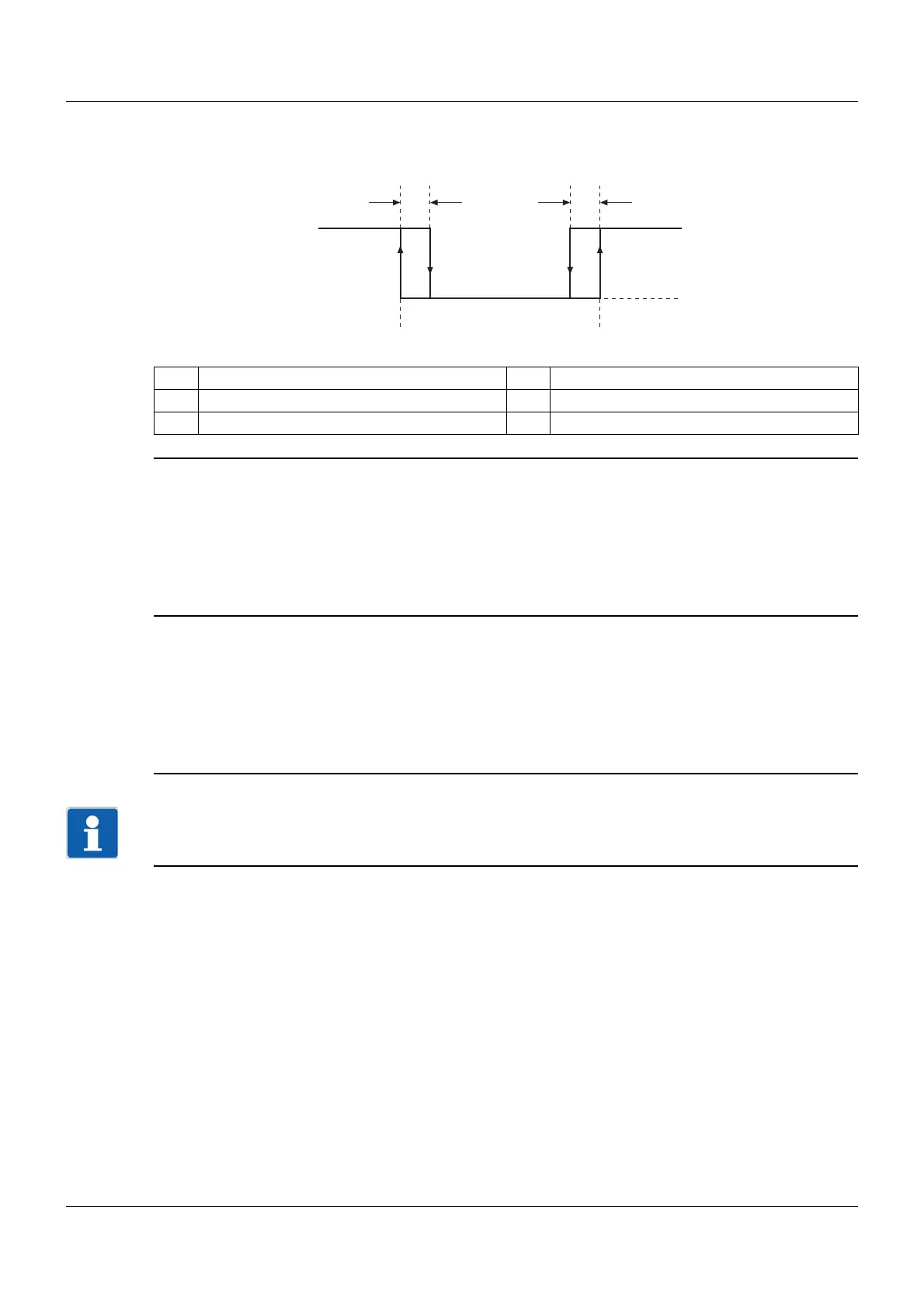
Example of tolerance band monitoring
The principle of the alarm follows the alarm configuration of the individual analog channels.
Channel 1: Measured value = 21°C (reference value)
Upper tolerance band limit = 10°C
Upper switching differential = -2°C
Channel 2: Tolerance band is active.
The alarm is generated if the current measured value from channel 2 is above 31 °C.
The alarm is canceled again if the current measured value drops below 29 °C.
Channel 1: Measured value = 21°C (reference value)
Lower tolerance band limit = -10°C
Lower switching differential = 2°C
Channel 2: Tolerance band is active.
The alarm is generated if the current measured value from channel 2 is below 11 °C.
The alarm is deleted again if the current measured value exceeds 13 °C.
NOTE!
In the example shown, channel 1 is constant and channel 2 changes its measured value. This does not
have to be the case. It could just as easily be channel 1 that changes, or even both channels.
(1) Lower alarm 1 Alarm on
(2) Upper alarm 0 Alarm off
(3) Switching differential