JVL Industri Elektronik A/S - User Manual - Integrated Stepper Motors MIS23x, 34x, 43x 103
6.4 Gear Mode
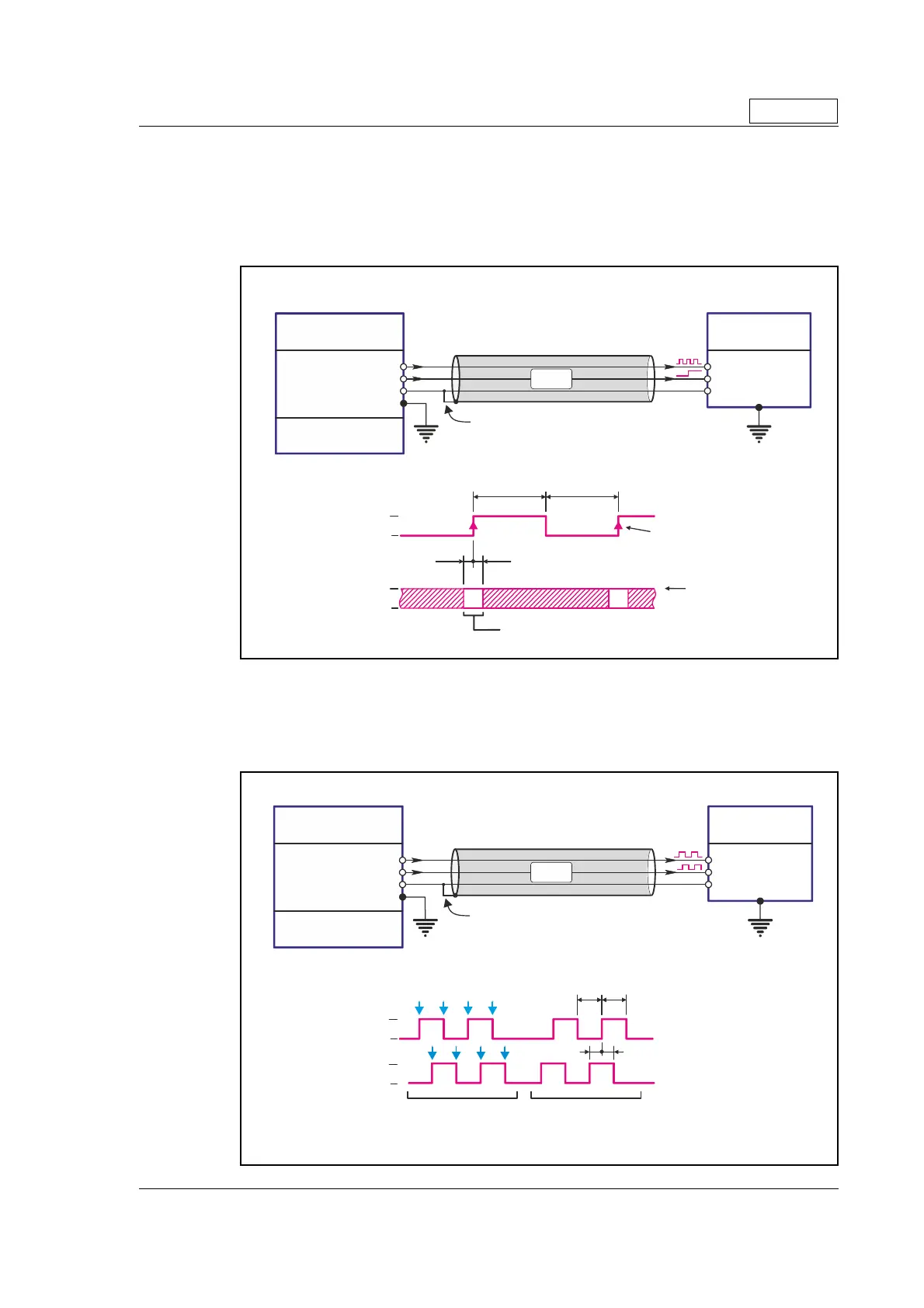
6.4.6 Signal function and timing (only MIS23x).
The description below shows how to connect the pulse source when using the pulse and
direction format. Also the timing is shown. Please be aware that if the indicated minimum
timing is not respected the motor may loose some of the step clocks and the position of
the motor will end up being out of synchronism with the pulse generator.
The description below shows how to connect the pulse source when using the quadra-
ture format. Also the timing is shown. Please be aware that if the indicated minimum tim-
ing is not respected the motor may loose some of the step clocks and the position of the
motor will end up being out of synchronism with the pulse generator.
Only MIS23x
TT2172GB
Note ! : screen only
connected on signal source.
MIS23x
or SMC75
Screen
Step clock (IO1)
Direction (IO2)
Pulse and direction format - Timing and how to connect
Min. 5µS
Min. 2.5µSMin. 2.5µS
The Direction signal must stay stable and well defined
in the indicated period while the clock has a risin
ed
e.
Step occurs on the
leading flank
Motor moves CW when
direction is high (1) and
CCW when low (0).
Min. 5µS
IO2
IO1
GND
1
1
0
0
Step clock Output
PLC or Pulse
Generator
PNP (source) or
Push-Pull outputs
Direction Output
Ground
EE
Level definitions
Logic 0" = < 1.0V
Logic 1" = > 2.8V
"
"
TT24
4-
1
B
Note ! : screen only
connected on signal source.
MIS23x
or SMC75
Screen
Channel A (IO1)
Channel B (IO2)
Quadrature format - Timing and how to connect
Min. 2µS
Min. 2µS
Step occurs on each
transition on either
the A or B channel
Min.
5µS
Min.
5µS
IO2
IO1
GND
1
1
0
0
Channel A Output
Incr. Encoder
or other source
PNP (source) or
Push-Pull outputs
Channel B Output
Ground
E
E
Ch. A is 90 degree
ahead which will
cause the motor
to move
CW
Ch. B is 90 degree
ahead which will
cause the motor
to move
CCW
Level definitions
Logic 0" = < 1.0V
Logic 1" = > 2.8V
"
"

 Loading...