JVL Industri Elektronik A/S - User Manual - Integrated Stepper Motors MIS23x, 34x, 43x 29
2.7 Special Outputs
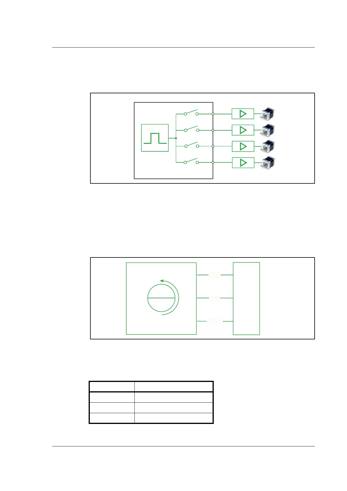
2.7.4 Pulse/Direction Outputs
Any number of the outputs can be configured to follow the pulse and direction signals
used internally in the motor. This can be used for accurate synchronization of two or
more motors.
See the register description for registers 108 and 109 in PulseDirMask, page 136 and Pul-
seDirMod, page 136
2.7.5 Encoder Outputs (only from version 2.0)
If the motor is equipped with a built-in encoder, it is possible to obtain the incremental
signal and the index pulse out on the user outputs. Please note that the voltage typically
is 24VDC PNP. Therefore a resistor to ground should be connected.
A 2 channel encoder with 256 pulses/revolution will give a total of1024 pulses/revolution.
If a magnet is mounted on the rear end of the motor shaft and this is placed in close dis-
tance to the SMC75 PCB, a 1023 pulses/rev. incremental A, B, index signal will be avail-
able on 3 of the output pins. Encoder position will also be available at an internal register
and can be used in a PLC program.
Output Encoder designation
06 A
07 B
08 Index
TT2230-02GB
Driver
SMC75
O1-O2
O3-O4
O5-O6
O7-O8
Motor
SMC75
N
S
PLC
TT2232GB
A
06
07
08
B
Index

 Loading...