222 JVL Industri Elektronik A/S - User Manual - Integrated Stepper Motors MIS23x, 34x, 43x
10.2 Connection and setup of the CAN bus
10.2.5 Bus termination
In order to guarantee correct operation of the CAN bus, bus terminating resistors must
be provided at both ends of the bus cable.
CAN bus connectors:
The MIS23x (SMC75) does not use 9-pin D-sub connectors and none of the cables JVL
supplies are provided with a 9-pin D-sub connector, but the PIN configuration is also
shown in the table below.
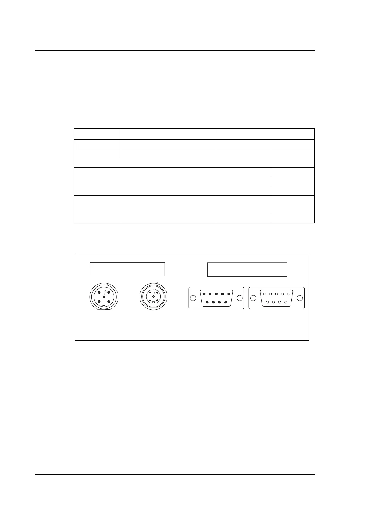
The figure below shows the 9-pin D-sub and 5-pin style connectors.
Signal Description MIS23x (SMC75) D-sub
- Reserved Pin 1
CAN_L CAN_L bus line (Low) Pin 5 Pin 2
CAN_GND CAN Ground Pin 3 Pin 3
- Reserved Pin 4
(CAN_SHLD) Optional CAN Shield Pin 1 Pin 5
(GND) Optional CAN Ground Pin 6
CAN_H CAN_H bus line (High) Pin 4 Pin 7
- Reserved (error line) Pin 8
CAN_V+ Optional CAN ext. + supply Pin 2 Pin 9
5-pin style connector
Male - front view
TT1
B
1
43
2
5
2
3
4
1
Female - front view
9-pin D-sub connector
Male - front view
Female - front view
5
1 2 3 4 5
5 4 3 2 1
6 7 8 9 9 8 7 6

 Loading...