JVL Industri Elektronik A/S - User Manual - Integrated Stepper Motors MIS23x, 34x, 43x 53
2.14 LED indicators at the MIS34x
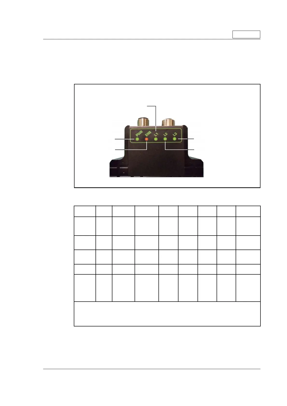
2.14.1 Indicator LED’s - description for products with Ethernet.
This description covers all MIS34x products with build in Ethernet such as
MIS34xxxxExxxxx (except MIS34xxxxEWxxxx
The LED's are used for indicating states and faults. There is one power LED, two link/
activity LED's (one for each Ethernet connector), and 2 status LED's.
LED indicator descriptions
LED Text Colour Constant
off
Constant
on
Blinking Single
flash
Double
flash
Triple
flash
Flickering
L1 Green
NMT_CS_
NOT_
ACTIVE
NMT_CS_
OPERA-
TIONAL
NMT_CS
_STOPP
ED
NMT_CS
_PREOP
ERATION
AL1
NMT_CS
_PREOP
ERATION
AL2
NMT_CS
_READY
_TO_OP
ERATE
NMT_CS_B
ASIC_
ETHERNET
L2 Green
No valid
Ethernet
connection.
Ethernet
is
connected.
- - - -
Activity on
line CN2
L3 Green
No valid
Ethernet
connection.
Ethernet
is
connected.
- - - -
Activity on
line CN3
ERR Red No error Error
Booting
error
PWR Green
Power is not
applied.
Power is ap-
plied to both
motor and
module.
Power is
applied to
module but
no communi
-
cation with
motor.
Notes:
Blinking: Flashing with equal on and off periods of 200ms (2.5Hz). Single flash: Repeating on for 200ms and
off for 1s. Double flash: Two flashes with a period of 200ms followed by 1s off period. Triple flash: Two flash
-
es with a period of 200ms followed by 1s off period.Flickering: Rapid flashing with a period of approximately
50ms (10 Hz).
Only MIS34x
TT2
7-
1
B
Error indicator
Power indicator
General status indicator
Indicator overview
Line activity indicator (CN2
Line activity indicator (CN3

 Loading...