JVL Industri Elektronik A/S - User Manual - Integrated Stepper Motors MIS23x, 34x, 43x 7
1.1 Non-programmable motors
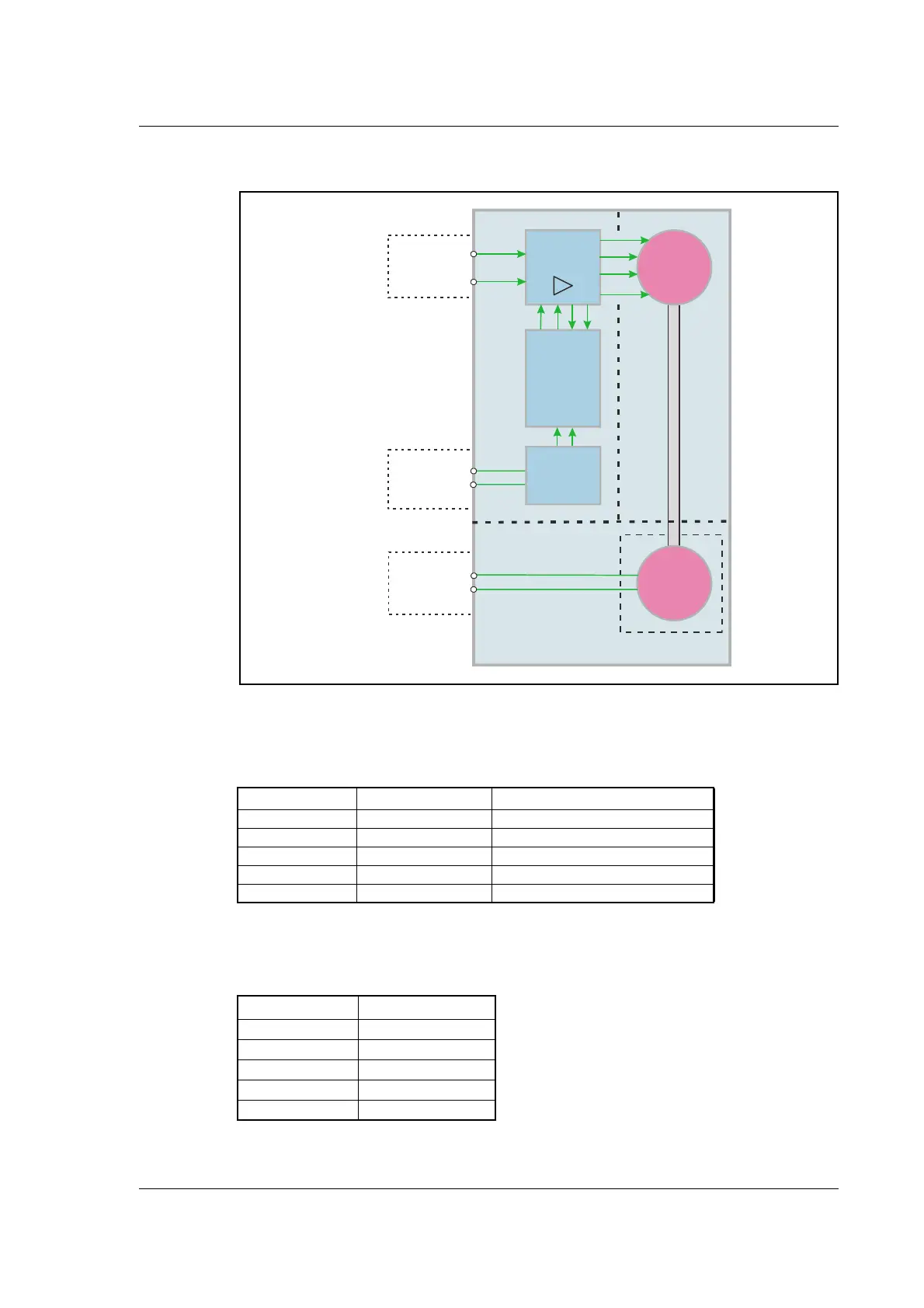
1.1.1 Block diagram, Pulse/Direction Version
1.1.2 Driver Connections
Versions with pulse and direction control:
Connections for versions with 1 M12 connector. (See also SMD73 data-sheet)
xx: 05 for 5 metre and 20 for 20 metre cable.
Versions with cable glands and 5 m cable
M12 5 pin male Description JVL cable WI1000M12 F5TxxN
1 P+ (18-28VDC) Brown
2 Pulse White
3 P- Blue
4 Direction Black
5 Signal Ground Grey
Colour Code Description
Red P+ (18-28VDC)
Black P-
Blue Direction
White Pulse
Shield Signal ground
2-phase
stepper
motor
Incremental
encoder
Optional
A
Stepclock
Direction
SMD73 or SMD74 Driver
Motor
Encoder
B
E
n
c
o
d
e
r
O
u
t
p
u
t
S
t
e
p
a
n
d
d
i
r
e
c
t
i
o
n
i
n
p
u
t
P
o
w
e
r
s
u
p
p
l
y
c
o
n
n
e
c
t
o
r
200, 400, 800,
1000, 1600 step
Driver
Bus Supply
18-28VDC (SMD73)
18-48VDC (SMD74)
Ground
High speed
digital logic
array
Phase A
Phase B
TT2178-02GB
5V to 24V
PNP/NPN
Selector

 Loading...