JVL Industri Elektronik A/S - User Manual - Integrated Stepper Motors MIS23x, 34x, 43x 17
2.2 Inputs
2.2.3 General
The Controller is equipped with a total of 8 digital inputs. Each input can be used for a
variety of purposes depending on the actual application. Each of the inputs can be detect
-
ed from the actual program that has been downloaded to the Controller or via serial
commands.
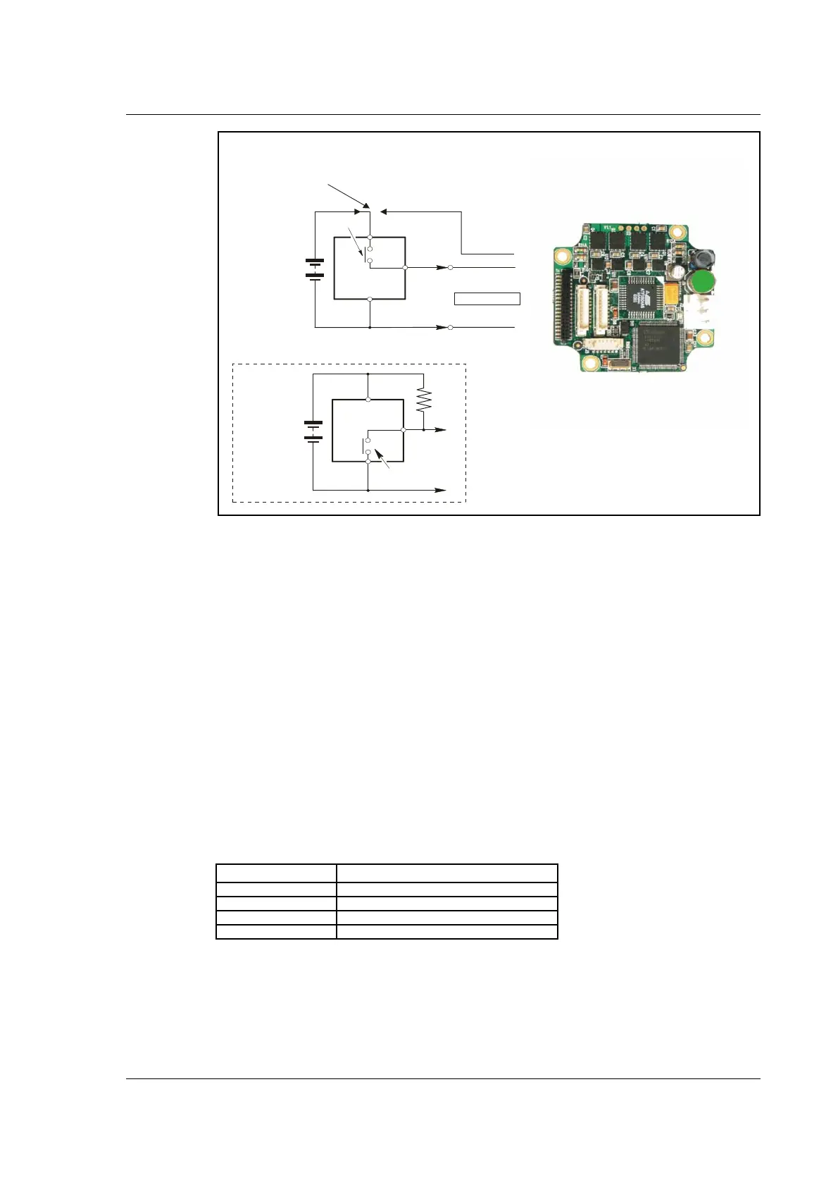
The Inputs are not optically isolated from other Controller circuitry. All of the Inputs
have a common ground terminal, denoted GND. Each Input can operate with voltages
in the range 5 to 30VDC. Note that the Inputs should normally be connected to a PNP
output since a positive current must be applied for an input to be activated.
Note that CVO is available as CVI on the I/O connectors. This provides the facility that
local sensors can be supplied directly from the controller.
2.2.4 Connection of NPN Output
If an Input is connected to an NPN output, a Pull-Up resistor must be connected be-
tween the Input and the + supply. See the illustration above.
The value of the resistance used depends on the supply voltage. The following resistances
are recommended:
Supply Voltage Recommended Resistance R
5-12VDC 1kOhm / 0.25W
12-18VDC 2.2kOhm / 0.25W
18-24VDC 3.3kOhm / 0.25W
24-30VDC 4.7kOhm / 0.25W
TT2161GB
Power Supply
+5-30VDC
+
Inductive
sensor
or similar
NPN Output
User I nputs
Power Supply
+5-30VDC
+
Inductive
sensor
or similar
PNP Output
CVO
This diagram is used if an NPN output is connected
R
Note that End-of-travel inputs,
I1-8 and HM share a
common ground ( GND).
All three ground terminals ( GND and P-)
are connected together.
Select external
or internal power
supply to sensors
or similar
cçê=~Åíì~ä=ÅçååÉÅíáçåë=
ëÉÉ=Çê~ïáåÖ=é~ÖÉ=NN
cçê=~Åíì~ä=ÅçååÉÅíáçåë=
ëÉÉ=Çê~ïáåÖ=é~ÖÉ=NN

 Loading...