36 JVL Industri Elektronik A/S - User Manual - Integrated Stepper Motors MIS23x, 34x, 43x
2.11 How to connect MIS34x
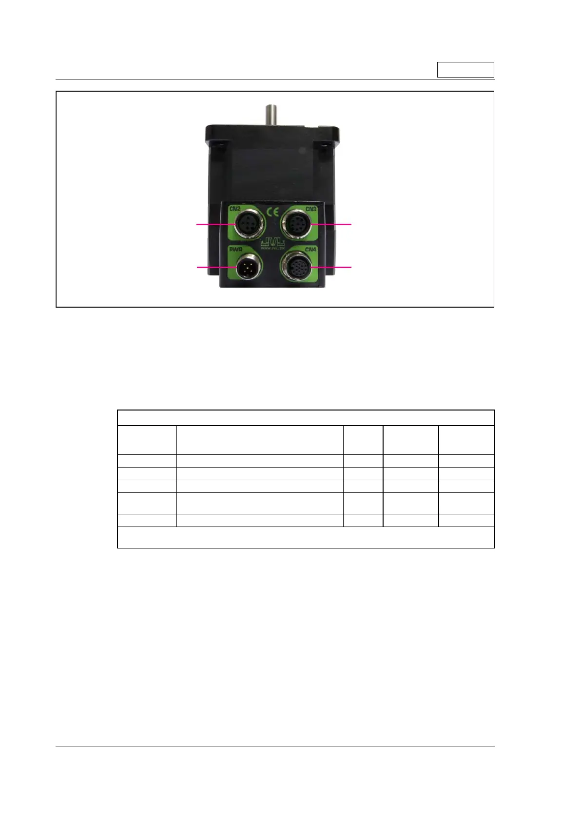
2.11.2 MIS34xxxxQ5xxxx connector description.
The MIS34x offers robust M12 connectors which makes it ideal for automation applica-
tions. The M12 connectors offer solid mechanical protection and are easy operate.
Following scheme gives the relevant information about each connector and the pins, wire
colours and a short description of the signals available.
The connector layout:
(Continued next page)
“PWR” (CN1) - Power input. M12 - 5pin male connector
Signal name Description Pin no.
JVL Cable
WI1000-
M12F5TxxN
Isolation
group
P+ Main supply +12-80VDC. Connect with pin 2 * 1 Brown 1
P+ Main supply +12-80VDC. Connect with pin 1 * 2 White 1
P- Main supply ground. Connect with pin 5 * 3 Blue 1
CVI
Control and user output supply +12-30VDC.
DO NOT connect >30V to this terminal !
4 Black 1
P- Main supply ground. Connect with pin 3 * 5 Grey 1
* Note: P+ and P- are each available at 2 terminals. Make sure that both terminals are connected in order
to split the supply current in 2 terminals and thereby avoid an overload of the connector.
Only MIS34x
TT2332-01GB.cdr
PWR (CN1)
Power input
CN2
RS485 IN/OUT
CN3
RS485 + I/O
CN4
RS485 + I/O + Backup(optional

 Loading...