76 JVL Industri Elektronik A/S - User Manual - Integrated Stepper Motors MIS23x, 34x, 43x
5.4 SSI encoder/sensor interface
5.4.1 General information on how to connect the SSI device.
The SSI interface is based on 2 differential lines.Both lines are available in the M12 con-
nectors and are named A1+, A1- and B1+,B1- (4 wires) -
In order to see the exact physical location of the signals please consult the pages:
- Connector overview for the MIS23x, page 33 and
- Connector overview for the MIS34x, page 35
The function of the signals is as follows:
- Line A1+ and A1- transmit a clock signal to the SSI device.
- Line B1+ and B1- receives the data stream from the SSI device.
5.4.2 Setup and operation of the SSI function when using MacTalk.
When using the MacTalk Windows program supplied by JVL the following descriptions
must be used.
There are a few differences between the different members of the MIS family.
MIS23x / SMC75:
No special setup is required. A read command will simply take care of reading data from
the SSI device if its connected as described above.
MIS34x / MIS43x / SMC85:
These products offer a very flexible interface for connecting many different devices.
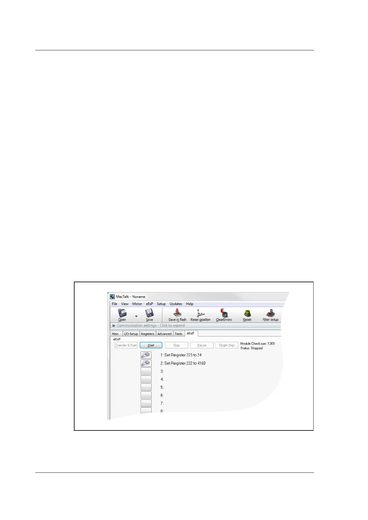
In order to setup these members for SSI support 2 codes need to be executed in a RxP
program. These 2 commands setup the RS485 interface covering the 4 lines to the SSI
device for transmitting a clock and receiving data from to/from the SSI device.
TT2479-01GB

 Loading...