JVL Industri Elektronik A/S - User Manual - Integrated Stepper Motors MIS23x, 34x, 43x 113
7 Error Handling
The MIS motor contains 5 fundamental parameters which are used for protection related
purposes. They all have effect regardless of which mode of operation the motor is set to
use.
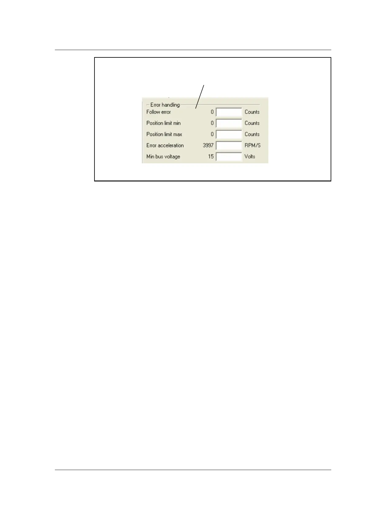
Follow error
(Only for MIS with internal encoder)
Follow error is the difference between the target position and the encoder position. The
target position is the position generated. Default is 0. (Function disabled).
Position limit min. and max.
Same as physical limit switches but implemented in software. Default is 0 meaning that
the feature is disabled. If one parameter is different from 0, both values are activated.
Error acceleration
If a fatal error occurs, it can be convenient to use a controlled deceleration instead of a
sudden stop. If the inertia in the system is high and the mechanical parts are weak, a sud
-
den stop can cause damage and unintended behaviour. Use this parameter to define the
deceleration used during a fatal error. Default is 0, meaning that the feature is disabled.
Min. bus voltage
This is the level of P+ at which the motor goes into error state “low bus voltage”.
Error Handl
ng
Use these fields to define error
limits for the maximum follow error etc.
TT2174G

 Loading...