JVL Industri Elektronik A/S - User Manual - Integrated Stepper Motors MIS23x, 34x, 43x 223
10.2 Connection and setup of the CAN bus
10.2.6 MIS23x connectors, rear plate layout
The MIS motors offer IP67 protection and M12 connectors which make them ideal for
automation applications where no additional protection is desired. The M12 connectors
offer solid mechanical protection and are easy to unplug.
The connector layout:
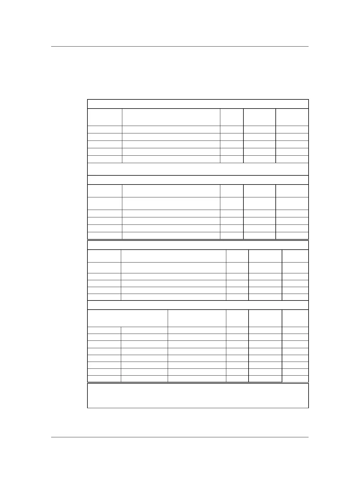
“PWR” - Power input. M12 - 5-pin male connector
Signal name Description Pin no.
JVL Cable
WI1000M12
F5A05N
Isolation
group
P+ Main supply +12-48VDC. Connect with pin 2 * 1 Brown 1
P+ Main supply +12-48VDC. Connect with pin 1 * 2 White 1
P- Main supply ground. Connect with pin 5 * 3 Blue 1
CV Control voltage +12-28VDC. 4 Black 1
P- Main supply ground. Connect with pin 3 * 5 Grey 1
* Note: P+ and P- are each available at 2 terminals. Ensure that both terminals are connected in order to
split the supply current in 2 terminals and thereby avoid an overload of the connector.
“BUS1” - CANopen interface. M12 - 5-pin male connector
Signal name Description Pin no.
Cable: user
supplied
Isolation
group
CAN_SHLD
Shield for the CAN interface - internally con-
nected to the motor housing
1 - 2
CAN_V+ Reserved for future purpose - do not connect 2 - 2
CAN_GND CAN interface ground 3 - 2
CAN_H CAN interface. Positive signal line 4 - 2
CAN_L CAN interface. Negative signal line 5 - 2
“BUS2” - CANopen interface. M12 - 5-pin female connector
Signal name Description Pin no.
Cable: user
supplied
Isolation
group
CAN_SHLD
Shield for the CAN interface - internally connected to the
motor housing
1 - 2
CAN_V+ Reserved for future purpose - do not connect 2 - 2
CAN_GND CAN interface ground 3 - 2
CAN_H CAN interface. Positive signal line 4 - 2
CAN_L CAN interface. Negative signal line 5 - 2
“IO” - I/Os and R485 interface. M12 - 8-pin female connector.
Signal name Description Pin no.
JVL Cable
WI1000-M12
M8A05N
Isolation
group
IO1 IO5 I/O terminal 1 1 White 3
IO2 IO6 I/O terminal 2 2 Brown 3
IO3 IO7
IO terminal 3
3 Green 3
GNDIO GNDIO Ground for I/O 4 Yellow 3
B+ Tx RS485 (5V serial) 5 Grey 3
A- Rx RS485 (5V serial) 6 Pink 3
IO4 IO8 I/O terminal 7 Blue 3
CVO CVO Out 8 Red 3
Cable Screen
Some standard cables with M12 connector offer a screen around the cable. This screen on some cables is
fitted to the outer metal at the M12 connector. When fitted to the SMC75 controller, this means that the
screen will have contact with the complete motor housing and thereby also the power ground (main ground).

 Loading...