48 JVL Industri Elektronik A/S - User Manual - Integrated Stepper Motors MIS23x, 34x, 43x
2.11 How to connect MIS34x
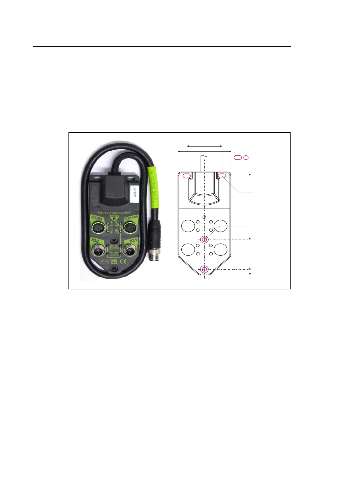
2.11.10 Drawing and description of PA0190
Junction box that splits the connects the signals in the MIS34x “CN4” 17 pin I/O con-
nector into 4 individual connectors giving an easy and more flexible installation.
Usage hints:
The LED's will only work with a MIS motor where the OUT+ and IO- is supplied from
the CN4 connector. See also the I/O description for the module.
If a cable is connected to the “BYPASS” then the Communication pins and GND must be
properly connected to valid signals (pins 2,15,17). AND “COM” must not be used. In
other words use EITHER the “BYPASS” OR the “COM” connector. Not both.
36.0mm
[1.42 inch]
54.0mm
[2.126 inch]
0
5.0mm
[0.197inch]
= Mounting holes
77.0mm
[3.031inch]
112.0mm
[4.409inch]
2 x
Ø4/8mm
[Ø0.16/0.32inch]
2 x
Ø4x8mm
[Ø0.16x0.32inch]
118.0mm
[4.646inch]
TT3088-01GB

 Loading...