JVL Industri Elektronik A/S - User Manual - Integrated Stepper Motors MIS23x, 34x, 43x 127
8.2 MIS23x Registers
8.2.16 Inputs
Description: This register shows the status of the digital inputs. Bit 0-7 shows whether IO 1-8 is
active or inactive. The active level can be set using IOSETUP. See IOsetup, page 140.
Bits 8-15 are not used and will always be 0. The inputs can be filtered or unfiltered. See
Input_Filter_Mask, page 143.
Note that all of the inputs have a digital state and an analogue value at the same time. This
register shows their digital state only. Note that the digital inputs can be filtered by set-
ting bits in register 135 (Input_Filter_Mask, page 143).
8.2.17 Outputs
Description: This register shows the status of the outputs. Bit 0-7 shows whether IO 1-8 is active or
inactive. The active level can be set using IOSETUP. See IOsetup, page 140. Please note
that the output driver for each output also has to be enabled. This is also done using
IOSETUP. The register can be changed in order to change the status of the outputs.
8.2.18 Flwerr
Description: When the encoder option is installed, this register shows the encoder deviation from the
calculated position (P_IST).
8.2.19 Flwerrmax
Description: The maximum allowed value in FLWERR before an error is triggered. If FLWERRMAX
= 0, the error is disabled. See register 35 (Err_Bits, page 129) for a description of the
error bit.
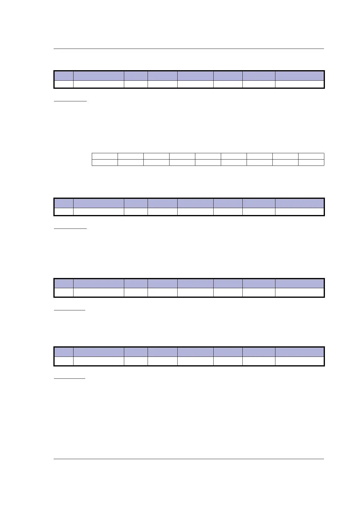
Reg Name Size Access Range Default Unit MacTalk name
18 INPUTS 16bit R - - Special Inputs
Bit76543210
Function IO8 IO7 IO6 IO5 IO4 IO3 IO2 IO1
Reg Name Size Access Range Default Unit MacTalk name
19 OUTPUTS 16bit R/W - 0 Special Outputs
Reg Name Size Access Range Default Unit MacTalk name
20 FLWERR 32bit R
(-2
31
)-(2
31
-1)
- Steps Follow Error
Reg Name Size Access Range Default Unit MacTalk name
22 FLWERRMAX 32bit R/W
(-2
31
)-(2
31
-1)
0 Steps Follow Error Max

 Loading...