74 JVL Industri Elektronik A/S - User Manual - Integrated Stepper Motors MIS23x, 34x, 43x
5.3 Absolute position back-up
5.3.2 Reading the Flash Backup data
The Error tracking and diagnostics counters can be copied to the general purpose regis-
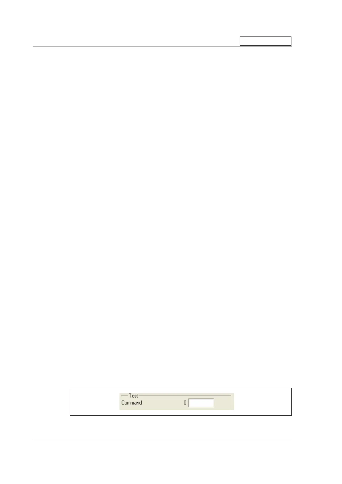
ter P1-8 and V1-8 by writing to the Command register 24. This can also be done by writ-
ing the value into MacTalk Command field on the Advanced tab and pressing Enter.
Saved positions, Run Seconds and counters
A command value of 260 will result in:
P1= Last saved values of the Actual Position, P_IST
P2 = Total number of times motor has been powered down
P3 = Total number of seconds the PCB has been running (with a valid CV supply voltage)
P4 = Total number of times a PLC program has been uploaded.
P5 = Total number of times the motor parameters have been saved to flash (button in
MacTalk).
P6 = Last saved external encoder value
P7 = Last saved SSI encoder value
V3 = Last saved Encoder position (internal magnetic encoder)
A command of 265 will result in:
P1 = Last timestamp (in Run Seconds) the Follow Error was set.
P2 = Last timestamp (in Run Seconds) the Output Driver Error was set.
P3 = Last timestamp (in Run Seconds) the Position Limits Exceeded Error was set.
P4 = Last timestamp (in Run Seconds) the Low Bus Voltage Error was set.
P5 = Last timestamp (in Run Seconds) the Over Voltage Error was set.
P6 = Last timestamp (in Run Seconds) the Temperature Too High Error was set.
P7 = Last timestamp (in Run Seconds) the Internal Error (memory test error) was set.
V1 = Number of times the Follow Error was set since the last Error Reset command.
V2 = Number of times the Output Driver Error was set since the last Error Reset com-
mand.
V3 = Number of times the Position Limits Exceeded Error was set since the last Error
Reset command.
V4 = Number of times the Low Bus Voltage Error was set since the last Error Log Reset
command.
V5 = Number of times the Over Voltage Error was set since the last Error Log Reset
command.
V6 = Number of times the Temperature Error was set since the last Error Log Reset
command.
V7 = Number of times the Internal Error was set since the last Error Log Reset com-
mand.
The command 266 will set all error timestamps and all error counters to zero.
All commands are entered in register 24 or in the Command field in Mactalk
Only MISxxx---H2---

 Loading...