270 JVL Industri Elektronik A/S - User Manual - Integrated Stepper Motors MIS23x, 34x, 43x
12.2 Step motor controllers (SMCxx)
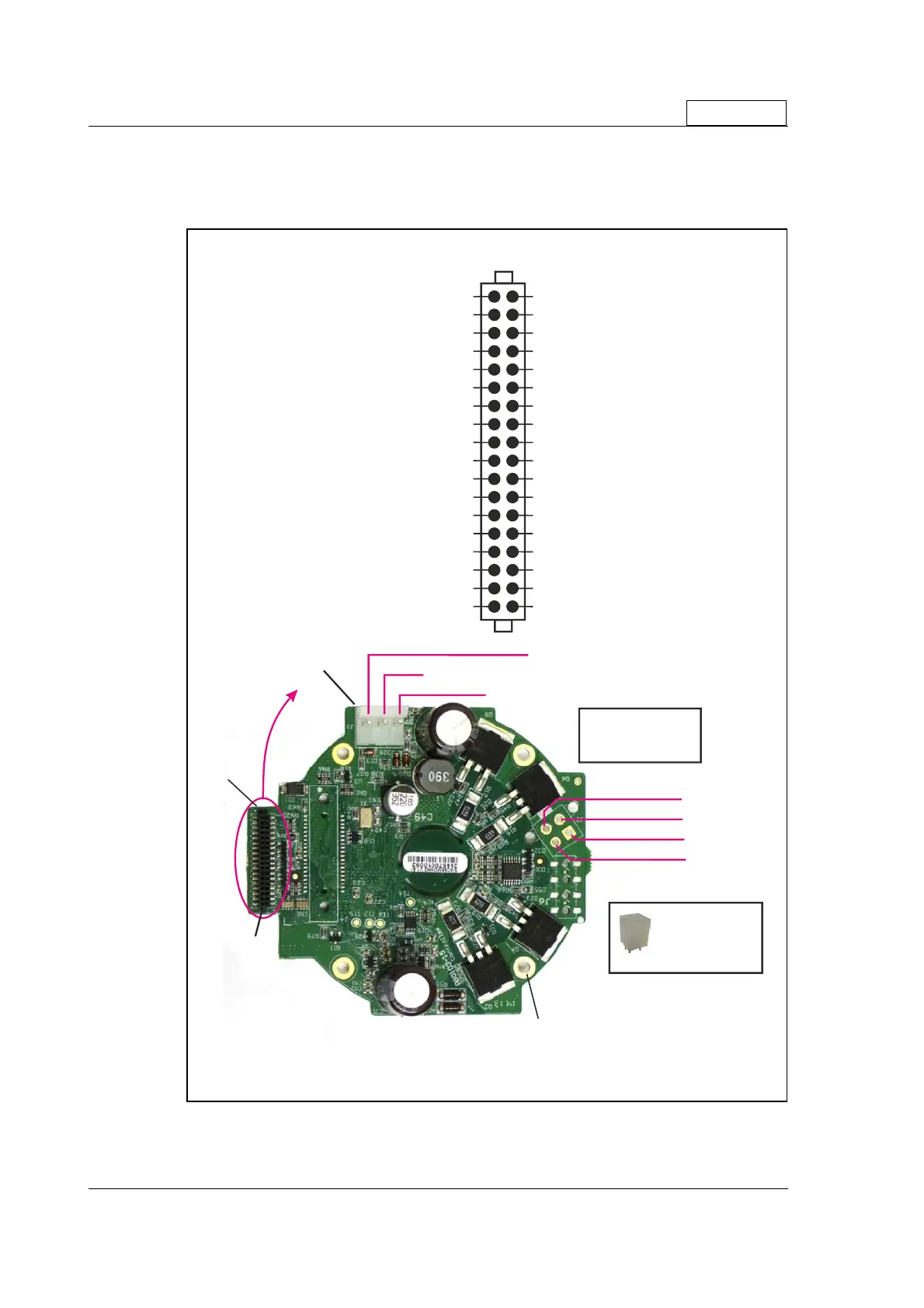
12.2.3 SMC85 Connector overview
The connections to the various connectors of the SMC85 PCB board is shown below.
Note that GND and P- are connected together internally.
Only SMC85
Do not connect !1 2
4
6
8
10
12
14
16
18
20
22
24
26
28
30
32
34
36
GND
(ground for I/O‹s same as P-)
Do not connect !3
GND
(ground for I/O‹s same as P-)
Do not connect !5
GND
(ground for I/O‹s same as P-)
Do not connect !7
GND
(ground for I/O‹s same as P-)
Do not connect !9
GND
(ground for I/O‹s same as P-)
(Conn. internally to CVI)
CV
11Not used - do not connect
(I/O channel 1)
IO1
13
+5V
out - max. 50mA !
(I/O channel 2)
IO2
15
RX
(RS232 receive - 3.3V !)
(I/O channel 3)
IO3
17
TX
(RS232 transmit - 3.3V !)
(I/O channel 4)
IO4
19
CAN_H
(optional)
(I/O channel 5)
IO5
21
CAN_L
(optional)
(I/O channel 6)
IO6
23
RS485 A-
(RS485 setup interface)
(I/O channel 7)
IO7
25
RS485 B+
(RS485 setup interface)
(I/O channel 8)
IO8
27
A1+
(RS422)
Do not connect !29
A1-
(RS422)
EA
(H2 enc. output optional)
31
B1+
(RS422)
EB
(H2 enc. output optional)33
B1-
(RS422)
Phase A+
Optional conn.
Molex series
Mini-Fit® Jr.
fits into the board
Phase A-
Phase B+
Phase B-
EI
(H2 enc. output optional)35
GND
(ground for I/O‹s same as P-)
SMC85C1AA - Bottom side
Connector J1 - pin description
Pin 1
Mounting holes (x4) Ø3.0mm
All have solid contact with
GND (ground)
TT2
-
2
B
I/O
- J1
Power
in - J3
Motor output
- J2
J3 pin 3 - (power GND)
P-
J3 pin 2 - (control supply 12-30VDC)
CVI
J3 pin 1 - (power 12-48VDC)
P+
Mating conn.
Molex series
SPOX™ and KK®

 Loading...