136 JVL Industri Elektronik A/S - User Manual - Integrated Stepper Motors MIS23x, 34x, 43x
8.2 MIS23x Registers
8.2.50 SSI_SETUP1
* Number of data bits. Clock frequency, Disable interrupts when Reading SSI
Description: This register contains status bits for the analogue input filters. The lowest eight bits hold
Register 107, SSI_Setup1, 16 bits: The low byte selects the number of data bits in each
SSI transfer. The valid range is 0 to 31, corresponding to 1 to 32 data bits. The high byte
selects the maximum clock speed in units of 10 kHz. The valid range is 0 to 59, corre-
sponding to 10 kHz to 600 kHz.
Due to the nature of the firmware timing some timing jitter can occur while reading SSI
data. Some encoders doesn't allow this or run with a very tight bit timing so that the
firmware timing jitter causes trouble. To prevent this, interrupts during SSI reading can
be disabled by setting the MSB of the high byte. In this way the timing is strictly control
led. If the timing isn't critical and the motor velocity is high we recommend that the in-
terrupts isn't disabled.
8.2.51 PulseDirMask
Description: The pulse and direction signals used to control the motor directly attached to the SMC75
board can also be optionally output to digital outputs and used to control other step-
per motors. The value in this register selects one of three operating modes: Mode 0
in which the pulse/direction signals are used only internally to control the motor attached
directly to the SMC75 board. Mode 1 in which the signals are not used internally but
output to the digital outputs selected in register 109. Mode 2 where the signals are used
both internally and sent out on the digital outputs.
See register 109 (PulseDirMod, page 136) for more information.
8.2.52 PulseDirMod
Description: When enabled by register 108, this register defines which of the eight digital outputs are
used to transmit the pulse and direction signals. The lowest eight bits select which
outputs will carry the pulse signal, while the highest eight bits select the outputs that
carry the direction signal. More than one output can be selected for each type of signal,
but the MacTalk program supports only one output for each signal. The outputs selected
here must be manually configured to operate as outputs using register 125
(IOsetup, page 140).
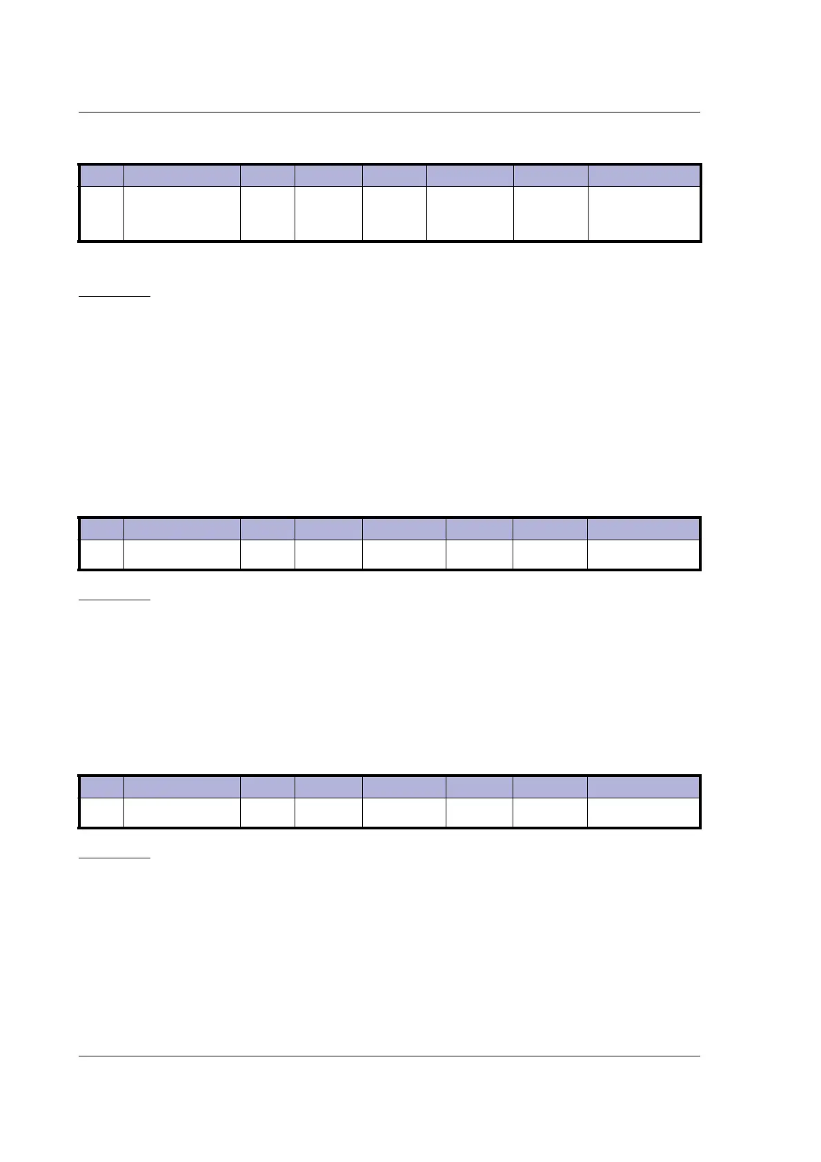
Reg Name Size Access Range Default Unit MacTalk name
107 SSI_Setup1 16bit R/W 16Bit
25bit, 100kHz
frequency pre
-
pare time
= 100µs
*
Reg Name Size Access Range Default Unit MacTalk name
108 PulseDirMask 16bit R/W 0-65535 0 Bit mask
Pulse signal
Direction signal
Reg Name Size Access Range Default Unit MacTalk name
109 PulseDirMode 16bit R/W 0-2 0 -
Pulse/Direction
mode

 Loading...