JVL Industri Elektronik A/S - User Manual - Integrated Stepper Motors MIS23x, 34x, 43x 23
2.4 User Outputs
2.4.1 User outputs
The MIS motors has 8 inputs/outputs (IO’s) that each can be set individually to input, out-
put or analogue input 0-5V via MacTalk or software commands.This means that it for ex-
ample is possible to have 4 inputs, 3 outputs and one analogue input.
Please notice: The number of available IO terminals available may vary de-
pending at which motor type you are using. Please the chapter Connector over-
view for the MIS23x, page 33 or Connector overview for the MIS34x, page 35
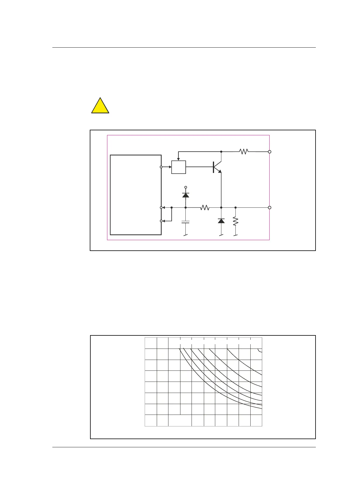
Input/output functional diagram:
• Outputs are Source (PNP) outputs and 5-28VDC compliant
• No galvanic isolation
• Short-circuit to ground protected that shuts down all outputs and sets Error bit in
software
• In Position and Error signal can be selected to be on any outputs 1 to 8
• Optional Encoder outputs
• 75 to 350 mA output current that depends on number of outputs activated and on
duty cycle. (See diagram)
• Internal ground clamp diodes
Allowable output current as a function of duty cycle
!
TT21
-
2
B
Internal µ-Processor
Digital input
CVI
<1 Ohm
10kOhm
1nF
4k7
+5V
IO1 to IO
Overcurrent protection
Analog input
Digital output
TT2180GB
0
0
39
78
117
156
195
C
o
l
l
e
c
t
o
r
C
u
r
r
e
n
t
(
m
A
)
234
273
10
20
30
40
8
76
5
4
3
2
50
Dut
C
cle
%
60
70
80
90
10
Number of outputs conducting simultaneously

 Loading...