JVL Industri Elektronik A/S - User Manual - Integrated Stepper Motors MIS23x, 34x, 43x 271
12.3 How to connect the motor
12.3.1 Cabling
For SMC75 controllers that supply a phase current in the range 0 to 3 A, it is recom-
mended that 0.5mm² cable (minimum) is used to connect the motor to the controller.
(0.75mm² is recommended.)
Motor cable lengths should not exceed 10 metres because of impedance loss. It is possi-
ble to use longer cables but motor performance will decrease.
Cables should be securely connected since a poor connection can cause heating and de-
struction of the connector. Similarly, tinned conductors should be avoided.
Important!
To minimise spurious noise emission from the motor cables and to fulfil CE require-
ments, shielded cable must be used.
If shielded cable is not used, other electronic equipment in the vicinity may be adversely
affected.
The removable connector must never be removed while a voltage is connected as this
will significantly reduce the lifetime of the connector. Note also that the connector’s life
-
time is reduced by repeated connecting/disconnecting since the contact resistance of the
pins is increased.
Note that P- is connected to the chassis and functions as the main ground on the Con-
troller.
See also Motor Connections Section 16.6, page 323, which describes how various models
of motor should be connected to the Controller.
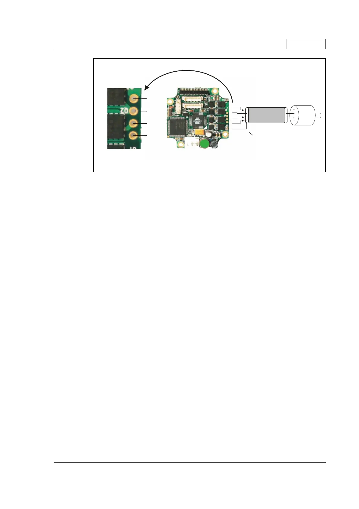
Only SMC75
Screen
Ste p Motor
Ground
Terminate screen only at SMC75
TT2168GB
A+
A-
B+
B-

 Loading...